Thanks for the thorough replies.
@harrisonpatm - I am planning to test the BMS when it arrives, set it's upper charge limit and check that if the power supply/charger exceeds this if it will correctly cut the power, I couldn't find any proper documentation for the BMS, so I was assuming this would be a 'standard' function.
13s because it best fits the voltage range of my application. It needs to be above 40v and below 50v, so I am planning on limiting the upper and lower voltage limits in the BMS to this.
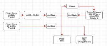
The reason for this is that I am using a few ideal diodes to act as source switchers, and to have the UPS battery as the lowest priority source it needs to be below the voltage of the other sources, whilst also being higher than the minimum input voltage of a Meanwell DCAC inverter (NTS-400P).
Here is a basic diagram of the design:
 @amberwolf
Thanks, for reference it is the 20a NMC version of this BMS:
https://www.aliexpress.com/item/1005006347440227.html?
primarily chosen for its compact size. Although I actually may have room for something larger if it is inadequate. It does claim a balancing function, but the documentation is very much lacking.
As mentioned above, I actually plan to limit the charge voltage to 3.85v per cell, so I guess this should provide me an extra layer of safety as the cells would have to be seriously out of balance to be overcharging from this source.
I am more than happy to buy higher quality or additional components to ensure the safety of the pack when charging, if there is anything I should add beyond what I have already mentioned.
The power supply - the RD RK6006 was chosen as RD seem to be a relatively well respected brand (for a Chinese vendor) in reviews on YT and such, and their DCDC PSUs are very easy to configure. If there was anything comparable from a higher quality brand (like Meanwell, or even other brands like TDK etc) I would be happy to consider. I haven't found anything remotely comparable in terms of size/ease of use.
Re: FET vs Contactor - I have no idea which my BMS is... but if I am making total guesses would I be right to assume that the cheaper brands like JBD use FETs? Can I ass a contactor inline to the BMS or does it need to be controlled by the BMS to allow the charging current?
The system actually would be regularly disconnected from source power (only in use during the day, disconnected overnight). But as you can see from the design above, the system is based around Ideal Diodes, so there should be no back-flow, the only thing that may have any drain would be the DCDC charging circuit, I'll test this when I have it in and add a diode for this as well if it's problematic. Thanks for the tip there!
edit:
Also are there any good resources on the forum regarding expected cell temperature at certain discharge rates?
I'm planning on using Eve 18650 25p cells. Which can support 20a discharge - but should I expect significant heat generation at this discharge? It is unlikely I will actually be drawing this much... but I would like to take it into my design consideration. There will be forced airflow through the UPS, so I can design the pack to take advantage of this.


