Hyena
10 GW
Hey guys,
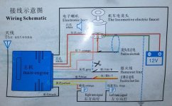
I'm in the process of wiring up a (cheap chinese!) motorcycle alarm for my new raptor build and am stumped with this wiring diagram.
It has 3 states: locked, unlocked and remote start. Even if I couldn't utilize the remote start I was hoping the on and off state could at least be used to turn my bike on and off but I'm not getting any voltage outputs in the areas you'd expect from the diagram below.
With the power, siren lights wired up it works as an alarm in that it chirps and flashes the lights when you lock and unlock. but the rest is a mystery.
Am I missing something with the switch set up? (that's "locomotive electric faucet" for those not versed in chinglish :lol: )
I would expect to get some sort of voltage output on the orange, pink or blue lines but I'm getting nothing.

The orange wire which is labelled "positive electrode" you would assume was a switched +12v right ?
Well no, and through probing around it's actually -12v between that and the main battery +12v (but isolated -ve through the alarm, ie not common earth)
The only thing is it's a fixed negative - it doesn't switch in any of the states - locked, unlocked or start.
There's also no voltage between that and any other wire in any state. There's also no output -ve or +ve on the blue wire, from any other alarm wire or main 12v source.
The only output at all I see from the alarm is a blink of +12v on the pink wire (to main ground) I press unlock. The only thing I can think of is maybe that's intended to trigger a latching relay (onboard a motorcycle normally?) but that doesn't seem right either.
I guess the other consideration is it was busted out of the box and I'm chasing my tail for nothing.
Any thoughts ?
I'm in the process of wiring up a (cheap chinese!) motorcycle alarm for my new raptor build and am stumped with this wiring diagram.
It has 3 states: locked, unlocked and remote start. Even if I couldn't utilize the remote start I was hoping the on and off state could at least be used to turn my bike on and off but I'm not getting any voltage outputs in the areas you'd expect from the diagram below.
With the power, siren lights wired up it works as an alarm in that it chirps and flashes the lights when you lock and unlock. but the rest is a mystery.
Am I missing something with the switch set up? (that's "locomotive electric faucet" for those not versed in chinglish :lol: )
I would expect to get some sort of voltage output on the orange, pink or blue lines but I'm getting nothing.

The orange wire which is labelled "positive electrode" you would assume was a switched +12v right ?
Well no, and through probing around it's actually -12v between that and the main battery +12v (but isolated -ve through the alarm, ie not common earth)
The only thing is it's a fixed negative - it doesn't switch in any of the states - locked, unlocked or start.
There's also no voltage between that and any other wire in any state. There's also no output -ve or +ve on the blue wire, from any other alarm wire or main 12v source.
The only output at all I see from the alarm is a blink of +12v on the pink wire (to main ground) I press unlock. The only thing I can think of is maybe that's intended to trigger a latching relay (onboard a motorcycle normally?) but that doesn't seem right either.
I guess the other consideration is it was busted out of the box and I'm chasing my tail for nothing.
Any thoughts ?


