chargery spam consolidated from discussion threads

Joined
Jun 16, 2023
Messages
11
Location
HK
Greetings everyone,

The C10325 is not just a power supply unit, but also a charger that can operate in three modes.

Firstly, it can charge a battery in Normal Charge mode. This requires selecting the battery type, setting the cell count, charge current, end current, end voltage per cell, and others every time.

Secondly, it can charge a battery in AUTO mode. When charge parameters are set, and AUTO charge is turned on, the charger can automatically charge according to the set parameters. This is very convenient, especially when charging the same battery repeatedly.

Thirdly, it can function as a power supply unit. However, to do so, the output voltage and maximum output current must be set.

When a battery is connected to the charger, it is assumed that the intention is to charge the battery. In this case, modes one and two are appropriate. If the PSU mode is used to charge the battery, all charge parameter settings are ignored. As a result, the charger will not stop charging or display "DONE" when the battery is fully charged. This is because all PSUs do not work at CC first then CV and stop as same as charger, even when a battery is connected.

Flippy has provided an excellent explanation of the differences between a PSU and a charger.

When the charger operates in Normal Charge or AUTO charge mode, it first measures the battery voltage and compares it to the set parameters. If they don't match, the charger will not charge the battery. For example, if the battery is a 10S battery, the minimum voltage is 27.5V, and the maximum voltage is 42.0V. If the voltage reading on the charger's LCD is 45V, the charger will not charge the battery. However, some BMS systems have a charging switcher that is turned off, preventing the C10325 from obtaining the battery voltage, resulting in no charging. At this point, if PSU mode is selected, the C10325 will output according to the voltage setting. The BMS will measure the voltage and turn on the switcher, resulting in charging current flowing into the battery. Although it may appear to be charging, it is not safe.

Some chargers will output voltage when the power switch is turned on, and they can work perfectly with the aforementioned BMS systems, charging the battery directly without checking the battery voltage. However, this is not safe if the battery is over-discharged or connected to the wrong type of battery, such as a 12S charger connected to a 10S battery.
 
What is the difference between new and used batteries?

Before assembling a used battery, it is important to test the capacity, voltage, and internal resistance of each cell. If the capacity difference is less than 5%, voltage difference is under mV, and resistance difference is under 1%, these cells can be connected in series or in parallel.

The whole battery capacity or discharge time is determined by the cell with the lowest capacity and the highest resistance.

Balancing the cell voltage using a BMS (Battery Management System) is the best solution. Since the BMS is installed with the battery pack, it constantly balances the cell voltage until all cells are balanced. If the cell voltage is not balanced, it may be due to the balance current being too small or the battery capacity difference being too large.
 
I'm building a 25s lifepo4 battery (25s1p, Headway 8Ah cells). Any suggestions on how to charge it? On my current 25s battery, I'm breaking it apart and parallel charging it as 5 banks of 5S batteries using a Chargery 1010B+ RC battery charger.

I would prefer:
- not having to break the battery apart - charge it as a single 25s battery
- add some type of BMS

Ideally, I would only want to charge it to 3.5v per cell, so something configurable would be nice. Charge rate is not so critical.

I see a Cycle Satiator would fit the bill, but that's about $350.

I'm also looking for suggestion for a BMS. I can't find anything that supports beyond 24s. I only need 40 amps, continuous. 5s

Thanks!
C10325B can charge 5S-28S LiFe battery, visit the link and buy, the manual is attached, don't charge battery on power supply, it is not safe and don't stop charging automatically.

for 25S battery, monitor 25 channel voltage by BMS is very important, if without BMS, the highest voltage cell or small capacity cell will be over-charged easily.
 

Attachments

  • Chargery C10325 charger manual V2.0.pdf
    1 MB · Views: 3
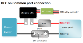
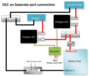
The most important step in assembling a battery pack is to connect each cell to the BMS. The battery pack's positive terminal is B+, and the negative terminal is B-. MOSFET (switcher) is present between B- and C-. C- is connected to the CHARGER output negative and the load negative (motor, inverter, etc.).

If the voltage on the battery side is 76V between B+ and B-, but on the BMS side, it is 72V between B+ and B-, this means that both B- terminals should not be connected together. If the voltage on B+ vs C- is 6.2V when the voltage is 72V, it may be incorrect. When the voltage is changed to 76V by checking the B- connection, the voltage on B+ vs C- should also change to 76V unless some cell voltage is not within the normal range.
 
The static power consumption is indeed very high, because it needs battery power to drive the coil continuously and keep it "closed." However, in case of any wrong events, it will be "OPEN," and the coil will be released, which is necessary for safety reasons.

In contrast, for SSR (mosfet type), the power consumption is very small and can be almost ignored. As for the CHARGERY DC contactor, it consumes only 11mA. The DCC is installed on the battery positive, and the BMS controls the DCC at 12V.

The external DCC has several benefits, such as saving battery energy and being able to flow a large current while keeping the BMS cool. A cool BMS (low temperature) ensures accurate voltage and current measurement.


DCConCommon.pngDcconseparate.png
 

Attachments

  • Chargery DC contactor manual V1.2.pdf
    1 MB · Views: 0
Last edited by a moderator:
The most important step in assembling a battery pack is to connect each cell to the BMS. The battery pack's positive terminal is B+, and the negative terminal is B-. MOSFET (switcher) is present between B- and C-. C- is connected to the CHARGER output negative and the load negative (motor, inverter, etc.).

If the voltage on the battery side is 76V between B+ and B-, but on the BMS side, it is 72V between B+ and B-, this means that both B- terminals should not be connected together. If the voltage on B+ vs C- is 6.2V when the voltage is 72V, it may be incorrect. When the voltage is changed to 76V by checking the B- connection, the voltage on B+ vs C- should also change to 76V unless some cell voltage is not within the normal range.
 
It is important to use a charger instead of a power supply unit (PSU) to charge any battery. For high voltage batteries (over 30V), the charger should have an anti-spark circuit to prevent damage to the charging terminal. it is better to protect battery from reverse polarity connection,.Additionally, the charger should have enough protection functions, such as how to charge a low voltage battery that is deeply discharged. The charging voltage and current must be accurate to protect the battery from overcharging on CV and from increasing charging time on CC.

Generally, voltage and current must be calibrated before shipping to ensure accuracy. inorder to charge batteries to different state of charge (SOC), the charge terminal voltage should be adjustable. To charge batteries with different capacity, the charging current should be adjustable as well. For most Lithium batteries, 1C is the maximum charging current. If charged at over 1C, the charging time will be shortened, but the battery will become hot, which may shorten the battery's lifespan.
 
It is important to use a charger instead of a power supply unit (PSU) to charge any battery. For high voltage batteries (over 30V), the charger should have an anti-spark circuit to prevent damage to the charging terminal.
This is contrary to the experience of very many of us in this forum.

I find that the only reliable chargers I've ever worked with are MeanWell PSUs and the Grin Cycle Satiator. And the Grin unit has a fragile, failure prone plug for the output cable.

Even the janky Chinese Li-ion specific chargers I've used spark when I plug them in. Like tire wear, it's just something to keep track of and address as necessary.
 
C10325B can charge 5S-28S LiFe battery, visit the link and buy, the manual is attached, don't charge battery on power supply, it is not safe and don't stop charging automatically
Sounds like a sales promo ?
..and is untrue, many PSUs do stop charging when the preset cut off voltage is reached..EG:- Meanwell and some clones thereof.
 
many PSUs do stop charging when the preset cut off voltage is reached..EG
if it is true, The PSU should measure the current at CV. When the current drops to zero, it may appear that the PSU has stopped charging.

However, on a battery charger, when the battery voltage reaches the preset charging terminal voltage, the charging current will drop automatically. When it drops to a preset current, usually 5% -10% of the current at CC, the charging must automatically stop because of the charger terminate PWM output. If the PWM is not cutoff, such as on a PSU, the current will drop till zero, which may appear as though charging has terminated. However, in reality, the PWM has not been cut off. When the battery voltage drops slightly, the current will go up again from zero.

For instance, if the charging current is 10A at CC, end current is 1A (10% of 10A) , when the current drops to 1A at CV, the charger should stop charging by terminating the PWM. Even if the battery drops significantly, the charger should not resume charging. On a PSU, at 1A, the PSU should not stop charging. However, when the current continues to drop to 0.0A, the charging will stop automatically, not because the PSU terminate PWM. When the battery voltage drops, the current should go up because the PSU does not terminate PWM. The lower the end current, the longer the charging time. From 1A to 0.0A, the time is very long. On a PSU, there is no need or ability to set the end current.

Generally, on a charger, when charging stops, the LED fully charged indicator will turn on. However, on a PSU, there is no indicator to show that the battery is fully charged.
 
Even the janky Chinese Li-ion specific chargers I've used spark when I plug them in. Like tire wear, it's just something to keep track of and address as necessary.
yes, In some chargers, there may not be an anti-spark circuit. These chargers have large capacitors on their output, which need to be charged when a battery is connected. This can be equivalent to a short circuit on the battery for a brief period, causing a spark to occur.

Large capacitors are also present on the output of a PSU, but there is usually no anti-spark circuit since batteries should not be connected to a PSU.
 
The static power consumption is indeed very high, because it needs battery power to drive the coil continuously and keep it "closed." However, in case of any wrong events, it will be "OPEN," and the coil will be released, which is necessary for safety reasons.

In contrast, for SSR (mosfet type), the power consumption is very small and can be almost ignored. As for the CHARGERY DC contactor, it consumes only 11mA. The DCC is installed on the battery positive, and the BMS controls the DCC at 12V.

The external DCC has several benefits, such as saving battery energy and being able to flow a large current while keeping the BMS cool. A cool BMS (low temperature) ensures accurate voltage and current measurement.
 
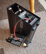
I got a chargery quite a while ago and yeah its decent does what it says in the tin but at the time i bought mine someone else on here did and posted the issue they had with it blowing up so its not god grade tech its chinnesium but its works fairly decent ive not come across any issues myself other than the main charging lead exits through a metal grill with a flimsy grommit so i swap the xt90 and lead to anderson powerpole fitted to the front of the unit so a short it much less likely from the cable rubbing on case with extended use.
 
As below.
 

Attachments

  • 20200926_162331.jpg
    20200926_162331.jpg
    3.1 MB · Views: 9
  • 20200926_162543.jpg
    20200926_162543.jpg
    3.9 MB · Views: 9
the anderson powerpole looks like very cool, i once try to find it, but don't find it where to buy,

for any suggestions, please let me know.

thanks
 
the anderson powerpole looks like very cool, i once try to find it, but don't find it where to buy,

for any suggestions, please let me know.

thanks
Here you go, hope this helps!

 
Back
Top