Charging Lithium Ion without BMS

Joined
Feb 19, 2008
Messages
418
Location
Peshawar, Pakistan
Dear All!

An idea, which came to my mind after going through so many, I would like to share with all of you nice people and would like to know your kind feedback, if any, would highly be appreciated by the undersigned.

Availability of lithium ion technology is almost none, except for cell phones in this region of the world. So I came up with this idea shown in the following diagram / figure. All cells are without any BMS and series connected to source giving out 14.4 volts as output.

Desktop chargers (input 220 volt) are available in the market in abundance with very low price. These chargers are completely automatic regarding charging a lithium ion cell and shuts off charging as it gets full. In this diagram four of them are connected to all the batteries all times.

Could any one tell me how much practical and applicable is this scheme?

Sincerely Yours
Naeem
 

Attachments

  • Charging Lithium Ion.bmp
    345.2 KB · Views: 927
As long as the chargers are indeed automatic and isolated, it should work fine. The chargers are *probably* "isolated" on their outputs, meaning that you can *probably* safely wire them in series like that.

You can check for isolation by using a multimeter on ohms, and checking the reading (with no power to the charger) from each AC input pin to each DC output pin. There should be essentially infinite resistance either way.

If there is a low reading on any of them, you probably can't use that charger in series with others, and would need to either disconnect each battery from the others during charge, or you would need to use only one charger, and physically connect to the first battery, charge it, disconnect it after charge and connect to the next to charge it, and so on.

What kind of Li-Ion batteries are you planning to use? (presumably on your bike?)


**a note regarding celphone battery chargers:
---typically, celphone batteries actually have a BMS built into every one of them. A little strip of PCB mounted right on the end under the shrink wrap, inside the plastic casing if there is one. The charger itself just supplies power to the phone, which then powers the battery to charge it and monitors the output line(s) from that BMS, which tells the phone when to stop.

---same thing for laptop batteries (which is another source of Li-Ion you might have out there that you could harvest).
 
amberwolf said:
What kind of Li-Ion batteries are you planning to use? (presumably on your bike?)

**a note regarding celphone battery chargers:
---typically, celphone batteries actually have a BMS built into every one of them. A little strip of PCB mounted right on the end under the shrink wrap, inside the plastic casing if there is one. The charger itself just supplies power to the phone, which then powers the battery to charge it and monitors the output line(s) from that BMS, which tells the phone when to stop. .

It is so nice to hear from you my dear friend. Thank you very much for your immediate response.

I’m planning to use cell phone batteries. Each battery will be stripped off and small BMS in plastic casing will be removed. 5 of such will be connected parallel to make a unit cell of having 3.6 volts. Then each pack (of 5 cells) will be connected in series to a maximum of 15 packs to get 54 volts. Each pack (total 15) will be charged using these desktop chargers. Another idea just struck my mind that we can use individual switches (high amps) between each battery pack to disconnect each battery during every charge.

I thank you again for your support, your kind attention and the time you take to respond my queries time and again.

Respectfully Yours
Naeem
 
You are a man who I know could figure out how to make cell phone batteries work, because you've got a fantastic combination of brains, ingenuity, and resourcefulness that is unable to be defeated.

However, just to ensure you are informed as well as possible before starting your project:

Cell phone batteries are seldom rated for more than 1C discharge.
Cell phone batteries have very high internal resistance, this means lots of heat, and lots of voltage drop.
Most cell phone packs are 1-1.5Ah, which would make even 5 in parallel be capable of <10amps of discharge.


I just want to make sure you are educated of these factors before starting.

If you set your mind to it, I've got full confidence you will make something work. :)
 
liveforphysics said:
You are a man who I know could figure out how to make cell phone batteries work, because you've got a fantastic combination of brains, ingenuity, and resourcefulness that is unable to be defeated.

Dear Sir,
It is always a big honour for me that you spare your precious time for me.
Thank you very much for your words of wisdom. Through the internet I learn a lot. There is an explosion of information out there so, to get the required information one wants is always difficult. I didn’t know about the precious facts you told me about cell phone batteries.

In my visit to the market I’ve come to know that old mobile models have there batteries very low price and in abundance. So it gives me the chance to go for my target objective, with approximately the cost of SLAs. Nokia 3310 is quite worn out model and have their batteries for Rs. 100 each (1 USD = 84.69 Rs.). I’ve got 15 of them with which I’m running some of the tests and taking the data after running tests. These batteries are about 900-1000 mili Amps I will keep on posting my test results. My target is to keep my bike low cost as well. So I better be careful this time not to cross this barrier.

Wish me luck.

Respectfully Yours
Naeem
 
I believe
One Picture = 1000 words

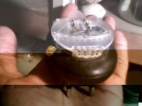
Here are some of the shots of Desktop charger and a pack of 3 Nokia batteries.

sincerely
Naeem
 

Attachments

  • Desktop charger1.jpg
    Desktop charger1.jpg
    32.9 KB · Views: 2,490
  • Desktop charger2.jpg
    Desktop charger2.jpg
    13.4 KB · Views: 2,488
do you mean having the batteries hooked up in a series then hooking up individual cell chargers to each cell and charging them that way? That's what I was thinking of doing too.
 
amberwolf said:
You can check for isolation by using a multimeter on ohms, and checking the reading (with no power to the charger) from each AC input pin to each DC output pin. There should be essentially infinite resistance either way.

If there is a low reading on any of them, you probably can't use that charger in series with others, and would need to either disconnect each battery from the others during charge, .

No Continuety when checked between each AC Pin with each DC PIN. It means that i can go with the afore-cited diagram (All AC wires joined togetter for a single 220 volt source), i guess ?

Looking forward for your kind response.

Naeem
 
You should be good to go there. Separate cell chargers are an excellent way to charge and balance.

You do need to be careful when discharging that no cell group goes below around 2v or permanent damage can occur. To be really safe, some kind of cell level LVC should be used. There are some fairly cheap units made for RC packs that could work. If you never get close to using the full capacity, you will be safe also.

This setup is much like Xyster used. If you do a forum search on Xyster, you can see his Li pack and charging setup.

If you can find enough batteries to make a large pack so that the discharge rate is within the cell rating (less than 3C), you will still be able to run the motor at normal power levels. For example, if your motor takes 20A, you should try to build a pack with at least 10Ahr or 20Ahr. This should greatly extend your range compared to the lead acid batteries (and weigh much less).
 
morph999 said:
do you mean having the batteries hooked up in a series then hooking up individual cell chargers to each cell and charging them that way? That's what I was thinking of doing too.

Dear Morph

What I mean was that 5 batteries will inititally be hooked up parallel to make a single pack of 5 batteries. then these 15 packs will be connected in series and all time the chargers (for each pack) will be connected all times. The AC 220 line of each charger will be connected to one source of 220 volt. I hope i make my self clear this time.

thank you very much indeed.

Sincerely
Naeem
 
fechter said:
You do need to be careful when discharging that no cell group goes below around 2v or permanent damage can occur. To be really safe, some kind of cell level LVC should be used. .

Dear Fechter!

Thank you very much indeed, and this comes straight from the heart.

Sir, i've made a UPS (uninterepted power supply unit) for my home, in which i used a circuit using 741 IC which cuts off the battery power when it goes some where below 10.5 volts. I think with some modifications I would be able to make it for each single cell or unit of cells in series to monitor for over discharge. if so the circuit should disconnect motor from the source pack, or a buzzer etc. could let the rider know about the pack damage is near.

About weight of the bike, I must share with all of you gentlemen that this time i've used 12 ah SLAs (4 of them rating 12 Volt and one 6 volt= 54 volts). the bike is so heavy that yesterday it snapped the chain on the wheel. It was quite davistating becuase i was about 2 miles away from home and i was in a big rush to office. It took me a local Rickshaw (3 wheeler) to pull me and bike with my hand holding one of the bar on Ricksaw. It was very dangerous I would say that it was quite a stunt, but i had no choice, i was getting already late. Then i took off on my Piaggio 125CC. It is quite disturbing to admit the fact that chain drive is the most un-reliable one. I'll start a tread soon about this topic also.

any way, thank you very much every body for hearing me out.

With warm regards
Naeem
 
fechter said:
You do need to be careful when discharging that no cell group goes below around 2v or permanent damage can occur. To be really safe, some kind of cell level LVC should be used. .
Regarding this, if there isn't a practical way to do it on every cell for any reason, you could also monitor the pack as two series halves, either with a comparator or with two volt meters and manually watch over it, *and* monitor the cell level of one cell in either side. The catch is, with a 15s pack, that's an odd number that can't be cut in half. :( If it was 16s or 14s, it would work fine, though. :)

Either of the conditions below should trigger your "LVC" circuit, either cutting off or restricting power output and/or alerting you.:
--If the comparison between halves "fails", meaning that they are significantly different in voltage
--If the single cell monitor drops to your LVC point

I am not sure what the "significant difference" should be in volts, but I would say no more than 0.1V per cell. If each half of the pack is 7 batteries, then no more than 0.7V total difference between the halves of the pack.

There's no guarantee that something not monitored in this way couldn't still go wrong, but it is better than no protection at all. ;)

There are people monitoring their car-sized EV packs this way, so it must be a workable solution, even if not the best one.

numberonebikeslover said:
About weight of the bike, I must share with all of you gentlemen that this time i've used 12 ah SLAs (4 of them rating 12 Volt and one 6 volt= 54 volts). the bike is so heavy that yesterday it snapped the chain on the wheel.
I'm rather familiar with problems like that, though mine has never broken a chain (except for when the overly-powerful motor kept pulling on a jammed chain), but I have certainly broken enough *wheels*. :( And the motor/chain has destroyed several chainrings.

But I have had many problems with the chain derailing due to problems with my chainlines, and I think also from frame flex due to how heavy the bike is. :( Since mine uses 3x 17Ah SLAs, at around 45 pounds of just battery, yours with at least 35-40 pounds of battery (maybe more) has got to be hard to handle when it is not under motor power, especially with it being taller and more of the weight higher up. (When I had DayGlo Avenger, the upright bike, motorized with 3x 12Ah SLAs, it was certainly hard to handle).
 
A chain is only as strong and reliable as its weakest link.

This is why quality is critical with a chain.

Size the chain correctly for the load it will be under, and then use a quality chain and sprocket set, and you will find it to be an extremely reliable power transfer method.
 
liveforphysics said:
A chain is only as strong and reliable as its weakest link.

This is why quality is critical with a chain.

Size the chain correctly for the load it will be under, and then use a quality chain and sprocket set, and you will find it to be an extremely reliable power transfer method.

With the option of derailing it (front and rare)at times, i guess the strongest and best chain will come under sircumstances that it will break. mine often breaks while i'm derailing it. as you could seen in the following pictues.

sincerely
Naeem
 

Attachments

  • derailers.jpg
    derailers.jpg
    65 KB · Views: 2,398
numberonebikeslover said:
I’m planning to use cell phone batteries. Each battery will be stripped off and small BMS in plastic casing will be removed. 5 of such will be connected parallel to make a unit cell of having 3.6 volts. Then each pack (of 5 cells) will be connected in series to a maximum of 15 packs to get 54 volts. Each pack (total 15) will be charged using these desktop chargers. Another idea just struck my mind that we can use individual switches (high amps) between each battery pack to disconnect each battery during every charge.

Hi Naeem,

I see you have a lot of passion for this stuff.

I'm pretty sure the Nokia cell battery has LVC protection, probably HVC and current protection too. Not sure what is the current limit, but using many in parallel it would not be an issue, and discharging them at greater currents may damage the cell anyway. I don't know about LVC and HVC precision, I assume HVC is a little high (maybe 4.3v) but I think using them as are with pcb could add extra protection. You don't need to rely on these, and could make your own protection circuit of course.
What are the reasons for striping off the small BMS circuits? Easier build (paralleling), current limit, or something else that I am missing?

I'm actually thinking to add two of those cell phone battery small BMS circuits to my stressed 2s RC pack that I'm using to power my bike LED lights for LVC protection. (I use them @ ~ 1A discharge).

Have fun,
Zsolt
 
kZs0lt said:
What are the reasons for striping off the small BMS circuits? Easier build (paralleling), current limit, or something else that I am missing?

Dear brother;

Thank you very much for your response.
In the beginning I thought that these chips (BMS) on cell phone batteries prevent them from making any parallel connection of these batteries for increasing Amps but it went well when tried it practically. In the afore-cited pictures you could see a parallel pack of three of them.

thank you very much for your precious time.

Naeem
 
Dear All:

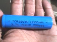
Thanks to Mr. Amberwolf who gave me the idea for harvesting Lithium ion from Laptop batteries. I went to the market today and found out the follwoing cells in the picture but i've no idea about the discharge current rate lvc and hcv. could any one of you tell me does the figures on the cell say something about it. These cells are made in China but a good quality ones. Rs. 160 a pcs. about 1.92 USD each. The thing about these cells incouraged me that this isthe most running item in the market now a days so its price is quite reasonable. Moreover, being a running item there is lesser chance that i may end up with a worn out cell lying in the shelf for years and as lithium ion do not have much shelf life. but yet i would need 42 cells to make my pack and that means waiting till i get rich enough to do it. any way i'm so happy about it. I've bought 3 cells at the moment and i'm running tests tonight. Oh God! due to curiosity I may not be able to sleep tonight so i'll do the experiments and test before going to bed.

wish me luck guys.

Naeem
 

Attachments

  • IMG0085A.jpg
    IMG0085A.jpg
    31.9 KB · Views: 2,108
Dear All

About the afore-cited laptop cells, I’ve got another idea. Just like in a small electric toy in which we use battery cells. We take them out for charging if they are rechargeable. Then put them back on in the compartment of the toy with a spring which hold the cells tightly together (in series most of the time). Using the same strategy I intend to make a pack of 4 cells in parallel as a unit and put them in a compartment in series provided with a spring to hold them tight and take them out for charging. In the bike there is also Low voltage cut-off circuit to prevent the cells go below the limit voltage (some where 2volts). While charging compartment/box makes all cells parallel, that is an ideal situation for such cells to balance more readily. The charger has a high voltage cut-off system to stop charging at certain point of voltage.

Moreover, if any one knows about the discharge current rate of these cells, would like to share any information about them will be highly appreciated.

Yours truly,
Naeem
 
numberonebikeslover said:
I went to the market today and found out the follwoing cells in the picture but i've no idea about the discharge current rate lvc and hcv.
I don't know that specific cell (didn't find it in a quick search online yet), but most of them are "LiPo", and like celphone batteries don't do high discharge rates or deep discharges very well.

I have a few hundred of them similar to yours that I am in the very slow process of testing and building into a battery pack (there's a link to the thread in my signature). Mine are 2000mAh and recommended at 1C max discharge, so only 2A max. Longer life is kept with only 0.5C discharge, or 1A max.

Mine are rated for 3.0V minimum voltage and 3.6V max voltage, with the standard charging rates and curves for LiPo. The data sheet for one of the kinds I have is linked in my battery thread, though it will be different for yours it might give you some basic idea of what they'll take.

EDIT (ADDED): I found an old "tentative" datasheet for an LG battery with that p/n (ICR18650) but it is for a lower capacity version, if it's even the same company:
http://www.all-battery.com/datasheet/18650A2%20TI.pdf

EDIT (fix): Actually, I just looked at the datasheet for mine again and found it's 2C *max*, but they give more power total at 1C, which is what I was thinking of. 0.5C would give longer life, too, I'm sure, but 2C is the max, not 1C. Probably same for yours.
 
numberonebikeslover said:
Just like in a small electric toy in which we use battery cells. We take them out for charging if they are rechargeable. Then put them back on in the compartment of the toy with a spring which hold the cells tightly together (in series most of the time). Using the same strategy I intend to make a pack of 4 cells in parallel as a unit and put them in a compartment in series provided with a spring to hold them tight and take them out for charging.

Nothing wrong with the basic idea; I think I have heard of it being done that way. The only problem is that you will need so many of the cells to get the voltage and current you need, that you will either have to have a lot of separate little cell chargers, or you will be swapping them out all night long to charge for the next day. ;)

I don't remember what your current requirements are, but at 42V (3x12 + 1x6, IIRC) you'd need to have at least 14 of them in series (assuming a nominal voltage of 3.6V during the flat part of the discharge curve).

Then, assuming 1C max discharge rate, that'd be 2.8A each string. If possible, I'd stick with 0.5C or 1.4A each string, for average discharge rate. They'll last longer. That means assuming oh, say 30A max draw and 15A normal draw, you'd need at least 10 series strings.

That's 14s x 10p, or 140 of those batteries.

Assuming 0.5C average, they'd then last you for about two hours of riding time before they were totally dead, but I'd also only take that down to 50% DOD (depth of discharge), which would be about 1 hour of riding time.


In the bike there is also Low voltage cut-off circuit to prevent the cells go below the limit voltage (some where 2volts). While charging compartment/box makes all cells parallel, that is an ideal situation for such cells to balance more readily. The charger has a high voltage cut-off system to stop charging at certain point of voltage.

I would set the LVC to 3.0V, or even 3.3V, rather than 2V. Almost all of the usable energy is gone by 3.3V anyway, on my cells, and 3.0V would only give a few more minutes use each time (with mine) and shorten cell life by perhaps a few hundred cycles!

The more you pull out of them total, the less cycles they will last you (just like pulling it out too fast.

HVC should be 3.7V on yours (as marked), but I would make it 3.6V. Charging to the max voltage *also* shortens life. :roll:
 
Back
Top