Cheap Charger Now Sending Overcurrent

wturber

1 MW
Joined
Aug 23, 2017
Messages
2,296
Location
Fountain Hills,AZ
This charger was only ever intended to be used temporarily and/or as a backup. I had such good luck using a MeanWell LED driver that my intention was to get one for the new bike and new 48v batteries. Nonetheless, if I can keep this charger from becoming e-junk, I'd like to do that.

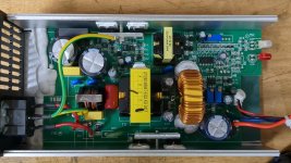
The charger was working fine until last night. It was charging a 35% full battery in a 93 degree garage when I left it. When I checked about an hour later, it was no longer charging. It is putting out the correct voltage, but the current output is measuring at slightly over 9 amps - and it is a 4 amp charger. Before I understood what was going on, I had blown the internal 5 amp input protection fuse on my three batteries. This is supposed to be a constant voltage and constant current charger. Even if I had a use for a 9 amp charger, I wouldn't trust running this at twice its rated output. So I'd like to fix it if for no other reason than I hate seeing stuff junked needlessly. Any thoughts on the most likely thing to have gone wrong? Ideas on ducks to shoot?


IMG_20240908_130428_737_SM.jpg
 
Have you played with the trimpots yet?

I did fiddle with the one at the top just to confirm it adjusts the voltage. I turned the other two a half turn (and back) and saw no change in current. I didn't want to go further than that and possibly get something else way out of whack. A half turn is easy to restore. I also didn't try further because the it seemed unlikely that a pot adjustment would account for a doubling of current output. That said, I suppose it is possible that the charger was borderline all along. I had never measured its current output before and had no ammeter monitoring things before fuses started popping. But even so, its hard to imagine that the output was much over the five amp rating of the fuses.
 
I can see what looks like the current measuring shunt near the trim pots RV1 and RV3 (R010). I would guess one of those pots controls the current. It's possible the pot went bad. You'd have to pull the board out of the case to trace the circuit to see which one it is. There could also possibly be a bad solder joint somewhere between the pot and the current sensing resistor.
 
I can see what looks like the current measuring shunt near the trim pots RV1 and RV3 (R010). I would guess one of those pots controls the current. It's possible the pot went bad. You'd have to pull the board out of the case to trace the circuit to see which one it is. There could also possibly be a bad solder joint somewhere between the pot and the current sensing resistor.
OK. That seems to be within my capabilities. Though I think they cemented the board to the case with some white caulky silicon stuff. So getting the board out will be fun. :)

Thanks
 
I can see what looks like the current measuring shunt near the trim pots RV1 and RV3 (R010). I would guess one of those pots controls the current. It's possible the pot went bad. You'd have to pull the board out of the case to trace the circuit to see which one it is. There could also possibly be a bad solder joint somewhere between the pot and the current sensing resistor.
R010 is attached to VR3. The resistance across VR3 is 114.3 ohms. The resistance across R010 is 0.2 ohms bleeding quickly down to 0.0 ohms resistance. Is the change in resistance to be expected since I'm not measuring the resistor in isolation from the circuit board? VR1 and VR2 measure 194.7 ohms and 179 ohms respectively.

So, it looks like I should try adjusting VR3 and see if the resistance changes in a predictable way as the screw is turned. If so, then see if an adjustment will make a difference.

FWIW, it turns out only one edge of the board was cemented in place. So no big deal to remove the board.
 
While poking around to see how the VR3 reacts to being adjusted I discovered that VR3 and VR1 are wired in series to each other and the shunt resistor. I seem to recall from other discussions that increasing the shunt resistance will typically lead to a lower current output. So I guess I'll make some adjustments and see what happens. I'm still bothered as to what caused the change to begin with given that both trim pots seem to be working correctly.
 
Well, there's clearly more going on than I understand. I put the board back in the case and fired it up and measured just more than 4 amps of output. Lucky guess on my VR3 pot adjustment? Seemed unlikely. So I went to tweak it to dial in exactly 4A and turning VR3 does nothing. Nada. Zilch. Amp output is rock steady as I adjust that pot. However, turning VR1 doeschange the current output nicely. But I was careful to make sure VR1 was returned to its original setting. So why was the output right near 4A on the first go if the VR3 adjustment has no effect? Also, it seems likely that there's more to the arrangement of VR3, VR1 and shunt resistor R010 than them merely being in series. Otherwise adjusting VR3 should adjust current output just as VR1 does.

So my current best guess is that some component is failing intermittently. It might be one of the pots and the mere act of turning their screws might have cleared the problem. Or it may be something else entirely. I guess there's not much to do now except to use the charger and see if if fails again. At least the batteries I'm charging seem to be reasonably well protected by their input fuses. So the risk seems small. Time to order that MeanWell.

Thanks for the input @fechter and @glennb
 
I don’t know much about the construction of those miniature pots, but it’s very reasonable that the wiper was gummed up or such and that by twiddling it you cleaned the contacts.

It’s also been a while since I poked around inside a charger, but vaguely remember one that had two pots to set current - one for coarse adjustment, and the other for fine adjustment. Which could be simply explained by the cost savings from using two crummy five cent pots instead of a single high precision five dollar pot. But there might be more to it, I’ve never had a high end power supply to look at / compare with.

FWIW, Meanwell also use those crappy little blue trimpots. I had a 5A “24V” one that I was using dialled up from nominal for 7S Li-Ion and 24v lead acid charging. The voltage adjustment trimpot failed after some years, which disabled the charger. You’d need to be good with a soldering iron to replace one. I needed it back in action pronto, so just bridged the pot contacts with a blob of solder (which is effectively nil resistance, resulting in charger outputting maximum voltage … 29.2 from memory, for this particular “24V supply).

Meanwells seem otherwise good though. I’ve only used the open frame ones though, can’t speak to the enclosed designs.
 
I’ve seen the wiper contact go bad on pots presumably from oxidation and simply exercising the pot makes it work again.
Not sure what the second pot is doing but it may be for some kind of short circuit detection.
 
Meanwells seem otherwise good though. I’ve only used the open frame ones though, can’t speak to the enclosed designs.
I've had a 42v 8A Meanwell LED driver mounted on my ebike for over five years now. It is the kind that has exposed Vo and Io pots (covered by rubber plugs) intended for the user to dial in the voltage and current output. I believe that thing is fully potted. No exposed vent holes or fans. That thing has been bullet proof for over 15,000 miles now. My intention is to get something similar with appropriate voltage and current outputs for the new bike.
 
I’ve seen the wiper contact go bad on pots presumably from oxidation and simply exercising the pot makes it work again.
Not sure what the second pot is doing but it may be for some kind of short circuit detection.
Yeah. I'll just start using it again and see what happens.
 
Back
Top