Commuter Booster - <1kg Friction Drive

Sorry for the slow reply. I am currently in holiday in Croatia.

Got the Soft On Off working nicely, but had a few packaging issues making it all fit in the enclosure I would like to use for the controller. So I have to make a trade off somewhere, or change enclosures to a bigger or custom one which I don't want to do yet.

I am also considering a customised off the shelf sinewave FOC controller that i recently became aware of that is looking very appealing. But holidays, and time zone differences have stopped me organizing the evaluation unit.

Damn life getting in the way of things.
 
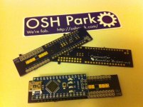
Long time coming.... finally here.
 

Attachments

  • CB Brains rev0.JPG
    CB Brains rev0.JPG
    63.8 KB · Views: 4,466
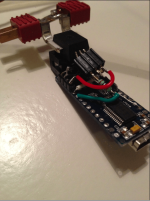
Nice with an integrated electronics unit. I soldered one up myself for testing purposes and put together a PI battery current regulation on the Arduino with a ramping feature. It would need some more work to automatically engage better but worked fine for my testing.

Screen Shot 2013-07-31 at 21.40.57.png

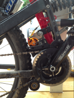
I also did fit my beta unit to my Nicolai UFO-ST full suspension frame, it did fit quite good in there and worked together with the suspension (but for full travel I would need to make a small cut in the delrin to allow more travel of the commuter booster pivot). What killed having the CB on this frame was the offroad tires making horrible noise on the motor can and the vibrations going straight into the saddle stem and continuing up... With an other tire it might be a nice setup.

Screen Shot 2013-07-31 at 21.41.19.png
 
Nice work.

My electronics have taken so long due to a huge amount of effort in testing limits of all the system, so I can have the smarts protect them. Plus the packaging nightmare off trying to keep everything small, light, clean, waterprooof, etc. Then the easy of manufacture stuff.... and on it goes. Oh and getting distracted by other controllers suppliers promising the world, and not delivering....

Regarding the knobblies and full suspension. The engagement angles are all quite deliberate when on a hadtail, so the geometry change due to suspension travel will change how well it engages and maintains drive. The CB betas were really design for road use, so the shock loads of off-road stuff may make life hard on the dead stops. Knobblies always suck for friction drives, but you can get off-road tires with a smoother central contact patch which work well. Regarding the vibration transmission through the frame, it may be possible to add some rubber between the CB clamp and the seat tube. Even old inner tubes work. They can dampen out some of the vibrations, but technically need the ID of the clamp to be increased to suit.
 
Hi,
first, thanks for your time about this amazing project, the best for me in term of usability and possibility to enjoy the true bike riding.
After that, please can you help me to understand which of this templates can be implemented on my bike ?
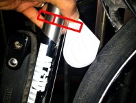
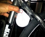
I know the problem with shifter cable but I'll try to do a clamp with groove to avoid interference like reported in red on the photo.
I need a motor just to have an help on climb at near 15Km/h and the bike is a 26'' , don't want a rocket bike,
so a low power and lighter system will do the job.
I'm looking at this motor but from my calc it will be powered max @3s (2S best) to be usable on a 26'' @ 15/20Km/h
http://www.hobbyking.com/hobbyking/..._brushless_outrunner_motor_eu_warehouse_.html

Lower RPM motors seem to be to huge to fit and have same problem because the diameter is bigger
http://www.hobbyking.com/hobbyking/store/uh_viewItem.asp?idProduct=36656

Thanks
Regards
Luca
 

Attachments

  • template_50mm_web.jpg
    template_50mm_web.jpg
    94 KB · Views: 4,260
  • template_63mm_web.jpg
    template_63mm_web.jpg
    97.8 KB · Views: 4,260
Adrian/anyone who can answer...

I'm starting an R/C friction drive build with a similar architecture and goals to Adrian's Commuter Booster build. I'm at the point of starting to test on-bike, but I don't have a high-buck e-Bike specific controller to use. I'm using a HobbyKing ESC and a servo tester.

But what I'd like to do is to be able to wire in a single-pole normally-open pushbutton switch to use to activate the motor. In other words, I'd dial in the speed I need for a given hill with the servo tester and then press and hold the button while doing the climbing (similar to the Commuter Booster pushbutton switch). It would also function to stop the motor if I let go of the switch (like when I had to apply brakes, or...fall :cry: ).

My question is: How can I wire in a pushbutton switch to do what I need? I tried wiring it into the (-) lead between the ESC and the servo tester, but when I let go of the switch the ESC kept the motor going for about 5 seconds before shutting down, and when it did, pressing the button again didn't start the motor - I had to power-cycle the ESC to get it to respond to the servo tester. I then tried wiring the switch into the (signal) line between the ESC and servo tester, with basically the same results.

Right now the only thing I can think of that might work would be to unsolder the pot from the servo tester and put the switch between one of the leads on the pot and the circuit board, but a) I don't know if that would work any better, and b) I'm not sure which lead to use.

I was hoping to do it without having to desolder or add anything to the ESC or servo tester (in other words, any mods would be to the cable between the two), but I'm willing to try my (de)soldering skills if need be. Anybody around with more EE experience that might be able to offer a quick bit of advice?
 
vadda said:
Hi,
first, thanks for your time about this amazing project, the best for me in term of usability and possibility to enjoy the true bike riding.
After that, please can you help me to understand which of this templates can be implemented on my bike ?
I know the problem with shifter cable but I'll try to do a clamp with groove to avoid interference like reported in red on the photo.
I need a motor just to have an help on climb at near 15Km/h and the bike is a 26'' , don't want a rocket bike,
so a low power and lighter system will do the job.
I'm looking at this motor but from my calc it will be powered max @3s (2S best) to be usable on a 26'' @ 15/20Km/h
http://www.hobbyking.com/hobbyking/..._brushless_outrunner_motor_eu_warehouse_.html

Lower RPM motors seem to be to huge to fit and have same problem because the diameter is bigger
http://www.hobbyking.com/hobbyking/store/uh_viewItem.asp?idProduct=36656

Thanks
Regards
Luca

Oops. Looks like I missed a few post here. Sorry for the slow reply.

If you can move the shifter cable either will fit. One option is to incorporate the cable lug feature currently on your frame into the clamp body friction drive that clamps around the seat tube. jsut need to drill a couple of holes and a slot in the plastic block.

As for motor. I definitely recommend the 59/63 mm diameter motors. Their larger size allow them to sustain a higher torque for a longer duration. Especially useful if you want to use the drive to climb long hills.

Run you calcs again. Remember at the no load speed the motor provide no power. So you want the diam/kv/voltage to give a speed greater than the assist speed you want. Also the greatest output power is at half the no load speed.

Good luck.
 
ahagge said:
Adrian/anyone who can answer...

I'm starting an R/C friction drive build with a similar architecture and goals to Adrian's Commuter Booster build. I'm at the point of starting to test on-bike, but I don't have a high-buck e-Bike specific controller to use. I'm using a HobbyKing ESC and a servo tester.

But what I'd like to do is to be able to wire in a single-pole normally-open pushbutton switch to use to activate the motor. In other words, I'd dial in the speed I need for a given hill with the servo tester and then press and hold the button while doing the climbing (similar to the Commuter Booster pushbutton switch). It would also function to stop the motor if I let go of the switch (like when I had to apply brakes, or...fall :cry: ).

My question is: How can I wire in a pushbutton switch to do what I need? I tried wiring it into the (-) lead between the ESC and the servo tester, but when I let go of the switch the ESC kept the motor going for about 5 seconds before shutting down, and when it did, pressing the button again didn't start the motor - I had to power-cycle the ESC to get it to respond to the servo tester. I then tried wiring the switch into the (signal) line between the ESC and servo tester, with basically the same results.

Right now the only thing I can think of that might work would be to unsolder the pot from the servo tester and put the switch between one of the leads on the pot and the circuit board, but a) I don't know if that would work any better, and b) I'm not sure which lead to use.

I was hoping to do it without having to desolder or add anything to the ESC or servo tester (in other words, any mods would be to the cable between the two), but I'm willing to try my (de)soldering skills if need be. Anybody around with more EE experience that might be able to offer a quick bit of advice?

Hey. Glad to hear you are making your own.

As for the push button throttle, I think you are going to have to break out your soldering iron. The servo tester takes an analof voltage from the POT and converts that to a PPM signal for the ESC. This signal is just a series of on/off signals. At zero throttle the on is for only 1ms at full throttle it is closer to 2ms wide. So when your button opens, the ESC no longer gets this signal and assumes the throttle is no longer present. Then some ESCs will require a power cycle to exit this error state.

The answer is to put your button on the analog signal of the POT. Could be as easy as cutting the centre leg, and putting the button in line. I am sure I documented this mod on this thread somewhere. If you are lucky it will be in the index page I start on the first post of the thread.

Two thing to keep in mind. Some of the cheap servo testers have some leakage current, that may cause the throttle signal to creep up over time even when your button is open. This will cause the throttle to come alive after a while. So watch out for that.

The second thing is current limitting. Even with the 59/63m motors if you don't have some form of current limitting you can over heat your motor.

That is it for now.

Good luck.
 
adrian_sm said:
The answer is to put your button on the analog signal of the POT. Could be as easy as cutting the centre leg, and putting the button in line. I am sure I documented this mod on this thread somewhere. If you are lucky it will be in the index page I start on the first post of the thread.

Two thing to keep in mind. Some of the cheap servo testers have some leakage current, that may cause the throttle signal to creep up over time even when your button is open. This will cause the throttle to come alive after a while. So watch out for that.

The second thing is current limitting. Even with the 59/63m motors if you don't have some form of current limitting you can over heat your motor.

That is it for now.

Good luck.

Adrian - thanks for the very informative answer. I searched and found a few posts, starting here, that seem to indicate that you had put the switch inline with the 5.5v input to the pot. But I couldn't tell if you used any type of pulldown resistor, as some of the posts indicate. Do you recall? And do you recall whether it worked as I described?

Update: I just tried wiring the button straight to the 5.5v line of the pot and it works as advertised. Genius, sheer genius!

And to your comments and those of spinningmagnets, yes, I do need to put in some low-ESR caps (anybody have a clue as to how many and a schematic showing exactly how they're wired in?) as well as current limiting. For the latter, I'm anxiously awaiting your new-and-improved Brain Box. Any noteworthy news to share on that front? :?:
 
Great to hear it worked.

BTW I have never used additional caps.

As for my electronics... I have come full circle and am evaluating commercial controllers again. My custom ones were great but cost way to much to make (labour costs) and required a lot of quality control overhead.
 
Kepler said:
Sound familiar Adrian. :)

With the recent availability of cheap, small and sensorless ebike controllers, its a whole new ball game for compact friction drives.

Fantastic thread, I am curious to build a friction drive myself.
With all the know how and experience you and Kepler have, what motor and controller combo would you suggest for a max 1000W basic setup today ?
I guess this might be difficult to answer but maybe you can give me some advice as to where to start.

Thanks.
 
Kepler said:
Sound familiar Adrian. :)

With the recent availability of cheap, small and sensorless ebike controllers, its a whole new ball game for compact friction drives.

Interesting... I admit I haven't been keeping up with the latest electronic goodies in this industry lately but a sensorless controller would be interesting for friction drive. I'm working on a couple of new projects that they might be perfect for.

I'm curious, with a sensorless controller isn't it true that you can't start from a dead stop? That might kill it for me right off the bat but if you can that would be great.

Also, do ebike controllers have some kind of rpm limit on them? On my current bike I need almost 9000 rpms.

When people started putting hall sensors on outrunners (sensored controller obviously) I thought that would be the holy grail but I think it was rpm limits that stopped me from trying it if I recall.

Do you have any links to the newer sensorless escs?
 
Hi,

As I can see, someone wants to use your concept.

With the minimum amount of modification.

http://www.gizmag.com/velological-worlds-lightest-e-bike-drive/31976/
http://www.velogical-engineering.com/home-en
 
Adrian,

Are you still planning a "next generation" product for sale, or have you given up on the idea? I don't have the metal- and delrin-working skills to make your bracket, and my attempts using wood in place of the delrin kept shattering. I'd still like to have one, but I'll need to purchase the mount from somone (I still have the motor & batteries).

Thanks for the update,

Alan
 
Hi Adrian,
Are the motor mounts still available for sale? I need one for 32mm tube. I tried emailing you a couple days ago, but I haven't got any reply so far...

Or maybe someone else can sell me theirs if they've got too many? :)
 
Hey Everyone,

Sorry about going incommunicado for so long. Life got a bit busy.... about the same time I realised that I don't think taking this project commercial is a good idea.

I was actually pretty happy technically, and still use this drive as my main ebike, but the business case just didn't stack up.
- too much support
- too restrictive ebike laws
- too much investment required to make it idiot proof enough
- and frankly too little money in it for the risk

Hence the other distractions in life like real jobs, and family taking over once again.

The question now is what to do with the development so far.
Like:
- mechanical drawings
- manufacturing/assembly step by step instructions
- test data
- Arduino Brain Box schematics, manuacturing/assembly notes
- Arduino Code (plus varients, like displayless PC programmable)
- Details of unreleased OEM controller, and scheamatic of minor mods to button throttle to work

Unfortunately is not in a nice clean state to make public that won't invite a lot of questions, and support.
I have never tried to make a development program open source that includes mechanical, electrical, and software. So would appreciate any advice.

Perhaps I just start with:
- eDrawing of 3D model of mechanical assembly
- Manufacturing notes for those that want to make there own
- Arduino code for those with existing Brain Boxes, plus "schematics"
- details of the new controller, for those that just want a dumb system that works without bells and whistles

What do people think?

- Adrian
 
adrian_sm said:
...I realised that I don't think taking this project commercial is a good idea.
Adrian,

Wow, that's a tough one. I'm sorry to hear that you don't have the time or resources to make a commerial product. I presume you've already considered the Kickstarter route...that would likely get you the funding you need to start up production, but wouldn't help out with the legwork of lining up manufacturers, setting up a business and everything else that goes with it.

But I can certainly understand your reluctance, given the myriad of laws that you'd have to deal with, though I wonder whether selling parts only (rather than a finished product) would help with that - but then you're back to massive customer support. Sigh.

In any case, I for one would be eternally grateful if you could/would release your work to the community as a whole. I suspect you'll have quite a number of questions for the first few months, but then hopefully things would settle down. Even just putting everything into a git repository (or up on Dropbox, for that matter) would keep your work alive and mean that all of those hard hours weren't for naught. And hopefully a small community would build your booster and help to continue your work, even if you were unable to.

Personally, the thing I'd most like to see is a 3d-printer-ready file for the mounting block. That's the one thing that I was never able to source. And maybe someday someone could make a nice eBike controller out of a Raspberry Pi... :D

But of course, the more you would be willing to open source, the better for the world at large!

Best of luck in your busy life and hopefully we'll see you here from time to time...
 
Wow, Adrian... That's sad...
I guess there are valid reasons why we don't see any real commercial products similar to your CB. Safety and idiot-proofing are the main concerns IMO. Having an exposed motor with sharp edges rotating at high speed in 5cm from rider's legs, and also having LiPos in a soft bag ready to explode on an impact will make safety certification a nightmare. And in the US, they tend to sue you to death if something bad happens. :shock: The protection measures will add bulk and weight, so the system will lose its main advantages.

That said, the idea itself is FANTASTIC for people who are ready to DIY and ready to take responsibility for their personal creations. For me, it all began when I just accidentally saw your avatar picture and instantly thought "This is exactly what I need!" I was even more excited when I've learned about the automatic variable engagement, and I personally think this is one of the most brilliant ideas in the whole ebike world.

I'm a hardware engineer, so if you need a hand tidying up the electronics documentation, I can help. I can also answer questions from the crowd after I get familiar with the circuit.

adrian_sm said:
The links from that post worked for me...
The code is there, but the schematic isn't. I'm currently only half way through this thread, so maybe later I'll consider using something else instead of the watt meter, however it would still be useful as a simple solution to get started with.
 
Hi Adrian,

Elegant design and beautifully fabricated, but understand your position.
Between engineering time, materials cost, fabrication time, and resolving my user-induced problems and bonehead qeustions... figure you probably netted something like 2 cents an hour on my Commuter Booster build.

Converting a hobby into a business often not the best idea.
Lots of work... check.
Little money... check.
Ample aggravation... check.
Probability that if and when it takes off commercially somebody will clone it and come to market with a knock-off just when things start looking bright... check.
Better to keep it on a hobby level and enjoy it.

That said, would be a real shame to just have your work on Commuter Booster fade away.
If you can somehow open-source the design and fabrication files without creating another time sink for yourself, please do.

Some general info on open-sourcing hardware designs: http://www.oshwa.org/faq/
 
Hi Adrian,

Thanks for the update, and thanks for sharing all your work so far with the e-bike community. I guess the silver lining is that you have made the call about not going commercial at this stage rather than after investing too heavily.

I feel privileged to be an owner of a Brain Box then, a piece of history!

My wife loves commuting with it on her Dahon folder, about three and a half years now I think, although I don't think she ever looks at the display as it has spun around on the handlebars.

I must say I'm also surprised at the other parts of that build hanging in there too - a Mark 1 Kepler Drive, a non-skirt-bearing Turnigy 6374, and the original Turnigy Lipos. A couple of rear tyres have been the only component replacements! Running around 1000W power.

Merry Christmas!
 
Grinhill said:
Hi Adrian,

Thanks for the update, and thanks for sharing all your work so far with the e-bike community. I guess the silver lining is that you have made the call about not going commercial at this stage rather than after investing too heavily.

I feel privileged to be an owner of a Brain Box then, a piece of history!

My wife loves commuting with it on her Dahon folder, about three and a half years now I think, although I don't think she ever looks at the display as it has spun around on the handlebars.

I must say I'm also surprised at the other parts of that build hanging in there too - a Mark 1 Kepler Drive, a non-skirt-bearing Turnigy 6374, and the original Turnigy Lipos. A couple of rear tyres have been the only component replacements! Running around 1000W power.

Merry Christmas!

Come on! Everyone knows friction drive doesn't work.
 
Back
Top