Commuter Booster - <1kg Friction Drive

IDEAS: Modified Turnigy Watt Meter Display Options

Been toying with the idea of modifying the Turnigy Watt Meter, to act as the smarts for my Commuter Booster.
Part of this is to display information to the rider. I have two concepts at the moment
(Note: grey text means it changes as the diplasy cycles through some views.)

v0.1 is assuming the watt meter just has voltage, shunt and throttle inputs
- the focus is on the battery state
- plan is to roughly estimate battery state of change using the voltage, LiPo assumption, and guess # of cells base on voltage to give a % reading to 10% resolution.
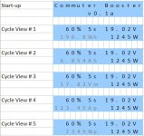
CB Computer - Display Layout v0.1a.PNG
v0.2 adds a wheel speed sensor input
- with a speed sensor, it opens up a lot more info to display
- the plan would be to have two display modes
1) while moving
2) when stationary
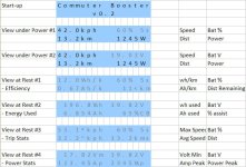
CB Computer - Display Layout v0.2.PNG

Distance remaining, would be an estimate based on average efficiency, and battery SOC estiamates
% assist, would be based on how many k's were assisted, versus total k's travel.

All just dreaming at the moment, while I try and see if I can actually do all this. But hey I can dream.
If nothing else it might give Kepler some ideas on what to display on his interface.

- Adrian
 
adrian_sm said:
That's the wrong motor, here is the one that Kepler ordered, which hasn't arrived yet I believe.
Which has a skirt bearing, see ...
kepler said:
This is the motor I ordered. http://www.leaderhobby.com/product.asp?ID=9394001220805
file.php

[EDIT] Fixed quote tags.

The 170 kv motor arrived yesterday. Looks very nice. I will do a bit of a mini review on it. Should I just post it in here or start another thread guys?
 
Awesome you got the motor. Looking forward to hearing if it is any better/worse than the HobbyKing ones. I get the feeling that they will be quite similar. Feel free to post results/review here. But it might be easier for others to find if you start a new thread.

On a related note I found a database of motor performance, that may be of interest. The main thing I am interested in is the efficiency, and therefore waste heat created by various motors. As it is ultimately this waste heat that limits how hard they can be driven. Only just found it so don't know how useful it will be.
http://www.peakeff.com/

This is the sorts of graphs it dumps out for each motor.
ctl00_ContentPlaceHolder1_Graph2S.png


On an unrelated note, I have been getting my head stuck in to Jonas's code for the Turnigy Watt Meter, and am starting to now be familiar enough with the assembler code, to understand how it all works. I am just adding notes (in english) to the code at the moment, and must say I am impressed with this little bit of hardware, and what Jonas has been able to do with it so far. It looks like I should be able to adapt this little bit of hardware to my needs, but will be limitted by the available memory for code. Hopefully it should provide a nice little DIY alternative to Kepler's WIP Interface.

- Adrian
 
Here are a few useful links for people that are thinking of modifying the Turnigy Watt Meter:

Where to buy the Watt Meter:
- $24 - Turnigy Watt Meter and power Analyzer

Jeremy's Remote Shunt Mod. Essential to get the watt meter up on the bars, and not have to run the battery cables up there too.
- http://www.endless-sphere.com/forums/viewtopic.php?f=28&t=22187&start=270#p350307

Download link for AVRStudio4Setup.exe. So people don't have to "register" to find the link.
You will need this to help write the code.
- http://www.atmel.com/dyn/resources/prod_documents/AvrStudio4Setup.exe

AVRFreaks.net Newbie's Guide To AVR Development:
- http://www.avrfreaks.net/index.php?module=FreaksArticles&func=downloadArticle&id=22

ATTiny 261 Datasheet. You will need this to understand how the uC works, and what all the commands etc are.
- http://www.atmel.com/dyn/resources/prod_documents/doc2588.pdf

DoctorBass's WattsUp Meter Schematic. Very similar schematic to the clone Turnigy Watt Meter.
Apparently there are a few discrepencies, but hey pretty damn close.
- http://endless-sphere.com/forums/viewtopic.php?f=3&t=13607&p=242804&hilit=schematic#p242804

Jonas's mods to the code, schematic, and hardware.
- http://www.endless-sphere.com/forums/viewtopic.php?f=28&t=22187&start=165#p337690
- [EDIT] Link to Google Translation to make sense of Jonas's swedish notes http://translate.google.com/#sv|en|

Full-throttle's list of appropriate programmers/debuggers that can be used:
- http://endless-sphere.com/forums/viewtopic.php?f=3&t=13607&p=331913#p331913

Programming header pin-outs:
- http://endless-sphere.com/forums/viewtopic.php?f=3&t=13607&p=331913#p332026

- Adrian
 
adrian_sm said:
IDEAS: Modified Turnigy Watt Meter Display Options

Been toying with the idea of modifying the Turnigy Watt Meter, to act as the smarts for my Commuter Booster.
Part of this is to display information to the rider. I have two concepts at the moment
(Note: grey text means it changes as the diplasy cycles through some views.)

v0.1 is assuming the watt meter just has voltage, shunt and throttle inputs
- the focus is on the battery state
- plan is to roughly estimate battery state of change using the voltage, LiPo assumption, and guess # of cells base on voltage to give a % reading to 10% resolution.
View attachment 1
v0.2 adds a wheel speed sensor input
- with a speed sensor, it opens up a lot more info to display
- the plan would be to have two display modes
1) while moving
2) when stationary


Distance remaining, would be an estimate based on average efficiency, and battery SOC estiamates
% assist, would be based on how many k's were assisted, versus total k's travel.

All just dreaming at the moment, while I try and see if I can actually do all this. But hey I can dream.
If nothing else it might give Kepler some ideas on what to display on his interface.

- Adrian

Very timely Adrian. My display has no problems displaying what you are proposing and it just so happens we are at a stage that we need to decide exactly what to display. My programmer is saying "well what do you want". I like some of your ideas but I need to condense them so that they can be displayed on a 2 x 8 LCD. I really like the different displays for stationary and moving. All to easy to provide too much info. I want to stick with what is the most useful to the normal rider
 
Ooh. 2x8 that is a bit more challenging.

Since your target market is the general public, and you have a small display, I would go minimalist.
I would actually avoid any power readings, and geek stats like wh/km.
Then maybe have a geek mode too look up this type of stuff.

So here goes my suggestion....
- Moving display just has speed and battery.
- Stationary display scrolls through 3 screens, Avg speed, Trip Distance, Assist distance remaining.
- User can scroll through stationary screens while on the move by pressing a button if they wish.
- Battery Full-> Empty gauge always displayed.
- Geek stats mode, entered via holding down the button. Then they either scroll through, or a button press to go through.
- Immediately reverts to Moving display when under power.
eBoost Display v1.0.png

- Adrian
 
Adrian,

Just wanted to pick on a couple of minor things:
Conventionally bargraphs have 'E' on the left and 'F' on the right.
Unless its a full graphic LCD, there's no 'empty rectangle character' in the LCD library. However it is possible to store custom characters in the EEPROM
 
Thanks full-throttle. Good to know someone knows what is possible in reality.
__________

Just thought I would post a useful link to the conversion between motor Kv, and the torque constant. This tells you how much torque the motor will provide for each Amp of current going through it. Obviously the possible motor current drops as BEMF rises with motor speed, but it can tell me what sort of thrust the motor is providing
Jeremy Harris said:
Kt (N-m/amp) = 9.5478 / Kv

So crunching the numbers for a few of the motors we are playing with:

5065-270kv, Kt = 0.0355 N.m/amp => Thrust of 1.42 N/Amp
6374-200kv, Kt = 0.0477 N.m/amp => Thrust of 1.52 N/Amp
6374-170kv, Kt = 0.0563 N.m/amp => Thrust of 1.79 N/Amp

No Load Speeds on 5s @ 3.7v = 18.5V
5065-270kv, 47 kph
6374-200kv, 44 kph,
6374-170kv, 37 kph, 45 kph (@6s)

All pretty similar, providing reasonable top speeds, and peak power at ~22-25kph. But :
- the little 5065 motor can't take a lot of waste heat. So for robustness sake would need power limiting.
- 6374 170kv, Gives a bit more torque, and allows 6s batteries, giving extra range for not much battery size penalty.

Actually once we have power limitting implemented, all of these motors would be happy run at a higher voltage, without the chance of overheating if done right.
The down side being that the ESC will have a harder life.
 
Update: Watt Meter Mods

After spending the last couple of days disecting the assembler code, to the point I understand how it works, I think I am going to abandon my grand plans to modify the Turnigy Watt Meter. The plan was originally to use this existing bit of hardware, with only simple modifications, to act as the brains for my friction drive. Thinking that if the modifications are simple enough, I could just make the updated code public, with some updated wiring instructions, and anyone could replicate it themselves.

But a few things are getting in the way:

1) Code space.
- Jonas's code already takes up 99% of the 2k space, no room for extra features without deleting other stuff

2) $$$'s.
- You still need to buy and additional ~$30 programmer to update the code.

3) Alternative #1
- Kepler's interface will hopefully soon be available for a very competitive price, with all the bells and whistles.

4) Alternatives #2
- Throttle interface, can be done with a simple mod to a $6 servo tester
- Ramp control can be done with a plug-n-play $8 servo speed regulator
- Battery capacity display, is just a nice to have, and there are heaps of solutions for monitoring/managing this.
- Minimum speed for drive engagement. Well for the DIY/enthusiast crowd, they will just have to not twist the throttle when standing still.
- Power Limitting. Again left to the user. But I would love something that can pull the throttle signal down, based on a current sensor reading.

I may still use Jonas's code (which nicely does the throttle interface, and power limitting) with a few very minor mods to give me a battery SOC (State of Charge) estimate and leave it at that. As that gives me most of the required features I need. But for the full wish list of features it would require transplanting a bigger ATTiny chip in to the watt meter, and that is just not worth the effort for me, and I imagine most others.

So a big thanks to Jonas for making his code available for others to use, and getting me interested enough to learn something new.

- Adrian
 
rj7855 said:
@adrian, What is (+-) the amount of movement between the idle and engagement stops?

I may be able to contribute a bit to the project, while I suck at metal working (and therefore probably unable to recreate the mounting hardware) I do have 30 years of experience with electronics and 25 in programming. I have made current sensing in the 100A range before... if I can find that design it would be easy to hook it up to an Atmel microcontroller in order to dynamically adjust throttle power. (it also could safeguard against "full throttlers" by limiting the ramp up of rev. up speed) it should not cost more than $20 to make.

@rj7855, Sorry I never did respond to this properly.

The +/- between the disengaged, and fully engaged stops is totally adjustable at the moment, via a couple of screw stops. But basically you don't want the drive to go over-centre on the tyre for the engaged stop, and the disengaged stop is set to give maybe 3-4mm clearence to the tyre. I have never actually measured the angles as I set this all up by eye, once I had the parts in my hand.

As for the current sensing pulling down the throttle, that is interesting. I have fairly simple solutions for most of the electronics drive problems except for limitting power. What do you think the simplest setup would be? A stand alone hall current sensor on a power lead, and some electronics trickery to pull down the throttle signal, like the cycle analyst does. Or would we be better off integrating it with the the function of the servo tester, and ramp regulator.

I would love something that can sit between a standard hall throttle, and the ESC, that does the following:
- creates correct throttle PWM throttle signal for the ESC
- user adjustable ramp up and down rates for the throttle
- dynamically adjusts throttle signal to keep current below an adjustable threshold.
Optional:
- speed sensor input, with a minimum speed threshold before allowing the throttle out signal to be active.

This would then allow tuning of all the basic important parameters for a friciton drive, and elminate the need to hack together other bits and pieces to get the electronics to work.

- Adrian
 
adrian_sm said:
As for the current sensing pulling down the throttle, that is interesting. I have fairly simple solutions for most of the electronics drive problems except for limitting power. What do you think the simplest setup would be? A stand alone hall current sensor on a power lead, and some electronics trickery to pull down the throttle signal, like the cycle analyst does.

I'm also interested in a simple solution to this but for hub motors and infineon style controllers. And my reasoning is to provide an "Economy" mode for max range and to encourage pedal effort for fitness. The Economy mode would provide 30% or so of full power but not be speed restricted. I'm also thinking that this should only apply to the pedelec control because that's a natural way of doing power on off with no thought. If you then have a throttle that is always active and overrides it, you have the control for short bursts of full power. So PAS only gives 30% power, PAS+full throttle or full throttle only gives 100% power. One of the tech problems with this is that (I think) most PAS sensors output a pulse stream and not a monostable +5v so you can't just feed the PAS signal straight into the throttle input of the typical Infineon controller.

Some of what you're talking about can be done with small mods to a CA so perhaps the simple solution is just to get one. But it doesn't do some of the RC specific functions you're after. There's enough there though that perhaps the CA could be slugged with some external analogue only circuitry to do the power ramp. But there's probably no way of doing the minimum speed for power on function.
 
Yep. CA technically can do the power restricting for me, as it could for you without limitting the speed like the speed switches on the "infinieon" controllers do.
But I was hoping to find a cheaper solution. One of the main aims for this project was to be not only simple and light weight, but also low cost. And requiring a CA to make sure you don't melt the drive I thought was a bit over the top.

If you are just looking to change the current limit of the XieChang controller on the fly, then you should be able to do this by tricking the shunt reading. I vaguely remember someone doing this, have a search and see what you turn up. I think others were doing it to be able to increase the max current of the controllers, by spoofing the signal to read lower than it should. So you should be able to do something similar but palce a switch in to be able to turn it on and off at will.

As for how that interacts with PAS, no idea. Never used one.

- Adrian
 
umejopa said:
Well Adrian now you have same setup as I have :D
Have make the current controll running better now and add a pot to set the level wene it with powerup.
Even more more snow here now so hard to test for me..

If you have time you can rebuld your Wattmeter and make it to RC-tester with current limit .
View attachment 2

Upload the hex code for the flash Watt1.hex and the EEdata Watt1.eep and assebler code if you want to change some.
The setting for current can ben set by the computer but for test it is better to have it adjusted on the road.
I think 1000W input may be a good limmit... (22V x 45A)

//Jonas
Original Post

Okay I have finally got around to putting Jonas's good work to use, but have a question on the wiring. I was planning on using a simple hall throttle, but it runs on 5V.
Will it work with 3.3V? Or should I pass through the 5V from the ESC throttle connection? As the Watt Meter doesn't have 5V available, everything is 3.3V.

So these are the connections I have planned
Throttle in: GND , 3.3V or 5 V, -> PA7 (via 10k, with 10k pull down)
Limit Pot: GND, 3.3 V, -> PA6
Throttle out: GND, None or 5V, -> PA4 (via 10k)

I am thinking 3.3V would be the preference as that means the PA7 is unlikely to see greater than 3.3V.

Here is Jonas's schematics for reference.

- Adrian
 
Reviewing random hall sensor spec sheets, it looks like I should stick with 5V. As they typically don't have a working range of input voltage that would work for both 3.3V & 5V.

So maybe that is why Jonas has a 10k resistor on the throttle in, to drop the voltage a little to an acceptable range for the uC ADC port PA7.
 
Man I am slow when it comes to electronics.

Okay, throttle in is via a 10k resistor with a 10k pulldown. So that should halve the voltage PA7 sees. So if it gets 4v out of the hall throttle, PA7 should only see 2v. All good.

So I just need to check the code to see what voltage range it is expecting.
 
adrian_sm said:
As for the current sensing pulling down the throttle, that is interesting. I have fairly simple solutions for most of the electronics drive problems except for limitting power. What do you think the simplest setup would be? A stand alone hall current sensor on a power lead, and some electronics trickery to pull down the throttle signal, like the cycle analyst does. Or would we be better off integrating it with the the function of the servo tester, and ramp regulator.

I would love something that can sit between a standard hall throttle, and the ESC, that does the following:
- creates correct throttle PWM throttle signal for the ESC
- user adjustable ramp up and down rates for the throttle
- dynamically adjusts throttle signal to keep current below an adjustable threshold.
Optional:
- speed sensor input, with a minimum speed threshold before allowing the throttle out signal to be active.

This would then allow tuning of all the basic important parameters for a friciton drive, and elminate the need to hack together other bits and pieces to get the electronics to work.

- Adrian

The electronics to this are really simple and most of it are needed anyway to translate the throttle signal (0...5 v analog) to a PWM signal that the ESC uses as input. (normally done by the servo tester many people use) The current can be measured by looking at the voltage over a shunt resistor (like the one of your power meter) or the voltage drop over the piece of cable that goes from the battery pack to the esc (as we´re talking fairly large currents these voltage drops are easily measured without using a dedicated shunt)
On the other hand using a shunt with known value would enable the possibility to implement that display you were talking about as all the ingredients are there (bat. voltage, current usage, speed).... and using a few extra parts it actually could be awesome ( add a sd-card and we could create a log file that allows you to analyze the trip afterwards, add a bluetooth module and we can send the data to a smart phone [ which in turn can combine your data with GPS data ])
Finally the speed sensor input can be made various ways but the most logical would be using the magnet & sensor from a cheap bike computer.

It´s a shame that in the coming weeks I can only use simulation and testing with a servo as my test ESC & motor are being delayed by the Chinese new year holidays.
 
I think the GPS, datalogging, Bluetooth etc is all cool but not worth it.

Kepler interface is almost ready, so a device with full feature set, display and all, is soon to be covered.

I think a very simple minimal device is what I am looking for. Something very cheap otherwise Keplers interface would be too attractive.

So what would be the simplest circuit to measure current and over-ride the throttle signal of a servo tester if the current is above a threshold?

- Adrian
 
Update: Commuter Booster "Brain Box"

Finally found a good enclosure for all the electronics, and managed to tuck away the ESC, modified servo tester, and ramp control into one tiny little box. With a little silicon it should all be weather proof.

This little 90x50x24mm (3.5" x 2.0" x 1.0") "brain box" now houses everything to drive the motor.

Inputs:
- Battery: 2-6s LiPo, Anderson PP45 connectors
- Throttle: Standard hall throttle, RC servo style connector

Outputs:
- 3x phase wires to motor, 4mm bullets

fr_440_size580.jpg
fr_432_size580.jpg
 
adrian_sm said:
I think the GPS, datalogging, Bluetooth etc is all cool but not worth it.

Kepler interface is almost ready, so a device with full feature set, display and all, is soon to be covered.

I think a very simple minimal device is what I am looking for. Something very cheap otherwise Keplers interface would be too attractive.

So what would be the simplest circuit to measure current and over-ride the throttle signal of a servo tester if the current is above a threshold?

- Adrian

The bill of material would be one micro controller (eg, an simple atmel) a few (less then 10) pot´s, resistors & capacitors,5 small wires to connect it to the bike electronics ( +5, 0 and pwm to the ESC and an two additional wire the connected to 0V near to the batteries and near the ESC; the current can be monitored by measuring the voltage drop between the two ground wires)
 
Have now made the hardware mods to the turnigy watt meter required to use Jonas's code ... with a few changes of my own planned :D
Link to Jonas's post

So I followed Jonas's schematic, plus:
- passed through the 5V from the throttle connection to the ESC, back to the throttle in connector for the hall throttle.
- used the LCD GND & 3.3V for the pot.

Now to reprogram and try the code... :D

fr_444_size580.jpg
 
Adrian this a great project.
Can you make a block diagram of the electronics box
I'm working on the motor mount when it is finished I will post pictures

Adried
 
Adried said:
Can you make a block diagram of the electronics box
Pretty straight forward, block diagram would be overkill.

ESC Throttle connector -> Servo Regulator -> Modded Servo Tester -> Hall Throttle connector

The hard bit is making it fit in the box. That took ages, but I wanted it small, and water proof.

Adried said:
I'm working on the motor mount when it is finished I will post pictures

Awesome. Can't wait to see it.
 
Update: Lights

Tried running my Magicshine headlight off the Turnigy Brushless ESC 85A w/ 5A SBEC, and it worked a treat. :D

5.5V@~1 Amps. So all I need to do is tap in to the throttles 5.5V line, which just happens to be up at the handlebars for throttle duties, and there will be light. :D

Now if only I had a cheap 5.5V red tail light I could have the full set. But all the ones I have are ~3V (ie. 2x1.5v batteries), and the only place I have 3V is if I have the Watt Meter installed, and that mounts up front on the handlebars. :x It is not really worth forking out $57 for the matching Magicshine tail light. Might just stick with a standard 2xAAA powered tail light, will be neater wiring anyway.

BTW if I was buying the headlight again, there is a newer alternative that looks good.

- Adrian
 
Back
Top