Hertzelz
Established
- Joined
- Jun 3, 2015
- Messages
- 51
Hey guys
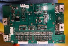
I just got this amazing beast; LLT 20s Li-Ion 200A BMS with Bluetooth;
https://www.lithiumbatterypcb.com/product/13s-16s-48v-or-60v-72v-20s-lithium-battery-bluetooth-smart-bms-54-6v-58-4v-67-2v-84v-electric-tricycle-pcb-with-200a-constant-discharge-current/
the seller has sent me to the website for instructions......................
but unfortunately the instructions in their website aren't very clear...
Anyone can tell me exactly what to connect in the correct order? don't want to damage this beast.
another thing, There's a 5v GND RST 3-pin input which I didn't received any harness for it, what is it exactly?
Thanks guys
I just got this amazing beast; LLT 20s Li-Ion 200A BMS with Bluetooth;
https://www.lithiumbatterypcb.com/product/13s-16s-48v-or-60v-72v-20s-lithium-battery-bluetooth-smart-bms-54-6v-58-4v-67-2v-84v-electric-tricycle-pcb-with-200a-constant-discharge-current/
the seller has sent me to the website for instructions......................
but unfortunately the instructions in their website aren't very clear...
1) Firstly , please connnect the B- bold wire to the Battery negative , take off the connector to make thin wires connection then connect first thin black wire to the Battery negative also , the next red wire to connect the first series positive port , ….then connect all wires strictly in order till to the battery postive port .
after connection finished of these thin wires, please measure all neighboring Pins voltage of the connector to make sure these voltages increased step by step at 3.7V~4.2V , if there is wrong connection order , the BMS will be damaged , after confirming the connection order , you can connect the balance wires connector into the BMS .
2) When connection finished ,please use the multi-meter to activate the BMS in the diode test mode , Black needle touch B- port and Red needle to touch the P- port ,then test the output voltage to see if it is equal with the battery voltage , if the voltage from Output is the same with the battery voltage , the connection is correct , please know it kindly
Anyone can tell me exactly what to connect in the correct order? don't want to damage this beast.
another thing, There's a 5v GND RST 3-pin input which I didn't received any harness for it, what is it exactly?
Thanks guys