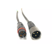
Connector Pin Diagram

its only 6 screws iirc retaining the motor cover which when removed will expose the other end of the cable and allow you to identify the three phase coils and sensor wire colours for splicing into your controller connection

As you know from the pinout for the julet connector from your controller in addition to the three phase coils ABC (generally THICKER blue yellow green wire) you have the +5v and ground feed for the sensors, (generally red and black), the three position hall sensor signal wires (often mirroring the coil colours abc) and a speed or temp sensor (often white)
 
You're going to buy a L915A and Z91 extension cables and make an adapter that will fit the MacFox to the current controller?

I bet that when you cut them open, you'll find three thick wires that are blue, green, and yellow. Also five thin wires that are red, black, green, yellow, and blue. Possibly a sixth white wire. I would take a chance and match the thickness and the wires together. I've done that with Z91 extension cables, and they use the same color sequence as controller cables and motor cables.

Or you can open the controller lid and inspect the motor cable, See if the bove motor colors come out to the circuit card. You can try tracing the ends to the pins in the connnector, Same as what fill suggests, except he looks at the motor. For me, I've never opened a motor, so I like looking at controller. .
 
Last edited:
My old motor failed.. i dont want to open new one cause if this doesnt work im going to return the tire. Im going to try to match color for color and pray i dont blow anything up.

Im doing exactly what you said i ordered new extention wire going to cut that, cut the one off the motor, and then see what happens

Im trying to get the new hub wire diagram just to double check things.
 
Back
Top