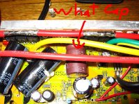
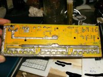
controller blew: EB318, lyen 18 fet

dfar

1 W
Joined
Jan 23, 2012
Messages
55
Hello

I recently decided to add more batteries to my pack and step the voltage up to 100volts from 80. Bike was working great at 80volts but I had the batteries just lying around so I decided to strap them on and see what 100volts would do.

With everything hooked up the bike would not move, I did not see any smoke etc. when I hooked everything together.

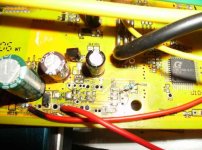
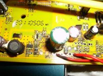
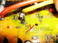
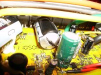
however when I took the controller apart to see If I could notice anything wrong it became quite apparent that something had fried (voltage regulator?).

as I am a complete noob to controllers I need some assistance in identifying the component/components that fried and what components to purchase and install so that this will not happen again.

controller is a 18 FET 72V 65A Brushless Controller EC-184110 (http://endless-sphere.com/forums/viewtopic.php?f=31&t=16605)

Thanks

Dfar

View attachment 2
View attachment 1
3.jpg
 
yep, it is supposed to split along the marks scribed into the cover so it doesn't blow out all over. i also like how you even cooked the power resistor like a hot dog. that should be in the fried guinea pig honor roll, imo.
 
dnmun said:
yep, it is supposed to split along the marks scribed into the cover so it doesn't blow out all over. i also like how you even cooked the power resistor like a hot dog. that should be in the fried guinea pig honor roll, imo.

I'm taking the "fired guinea pig honor roll" is one of those awards that you don't want to get and are not suppose to be very proud of being awarded.

like I said I am no expert but you seem to at least know the names of these components. I would very much like to learn about the controller and how to fix it (and use it within it's operating perimeters) so if you would be so kind to enlighten me or direct me to resources where I can learn about this it would be much appreciated.

what I can decipher from your post is that I fried the power resistor, and destroyed one of the capacitors.
 
ok so I figure I may have to replace the capacitors with 110 volt rated ones. But what I am trying to figure is what power resistor I need to use. Is there a formula that you can use to determine this? what is it based on? I'll continue my search in the ES archive.
 
how do you know what voltage you applied? did you measure with a voltmeter before you hooked up the controller?

the little IC next to the input power resistor may be the voltage regulator too, look for part numbers on it if you can read it. since the 3 terminal regulator may have blown up, the voltage may have shorted through it to the 5V regulator and also to the other mosfet drivers on the 12V rail and that voltage woulda been way too high for all those components too so i suspect they are burned up too.

there is no 110V capacitor that i know of. not sure of what the voltage really was that you applied.

edit: the Q13 is what i was thinking is the 12V regulator, but that spool next to it looks like an inductor so it may use a DC-DC converter for the 12V regulated input. so Q13 may not be a regulator but the IC controller for the converter. since the big cap that split is on the S/D buss then the mosfets also saw high voltage but they don't look burned up, but it never ran under load so they may be ok.

i think it will be a lesson to fix it for sure, kinda how everybody learns, not sure who has them and can help you find the parts. if the 5V rail was hot from shorting to the input voltage then the microprocessor coulda gotten overvolted too so that would be the first thing to determine, otherwise totally wasted effort to make it run again. imo

edit^2: maybe the Q13 is a power mosfet for the switching for the dc converter, the green cap at 100V is on the red wire which is your input voltage for the circuit current and the big red wire with 12AWG on it is the power to the output mosfets and runs over to the source rail with the caps on it. they will all be suspect now too from overvoltage. the zener diode in the upper left above the inductor on that perforated yellow section maybe is the diode for the dc converter and the other discrete parts in that burned section may be related to that, not sure. you can unsolder the burned up input power resistor and see what the resistance measures with a meter, but you want 5W instead of 2W if it gets that hot. but cut out or unsolder the blown caps, then try putting 12V on the 12V rail by using a small 12V battery, then see if you can find 5V on the 5V rail, and if you can then see if there is 5V on the hall sensor power lead, the red wire, and see if there is 5V on the throttle power lead. if that is the case and you have 5V you can then test the microprocessor by seeing if the hall sensors will toggle when the 5 pin plugf is connected to the motor and you rotate the wheel. if they toggle that means the microprocessor works, so may be worth some effort then. but no idea how to identify the parts from the codes on the Q13, but it may actually still be ok. never know.
 
dnmun said:
how do you know what voltage you applied? did you measure with a voltmeter before you hooked up the controller?

The cycle analyst showed 100.4v when I plugged everything in. I also checked the battery with a voltmeter and it showed the same. I did not use a precharge resistor on the battery/controller cables, could this have caused the failure? to high an influx of current?

dnmun said:
the little IC next to the input power resistor may be the voltage regulator too, look for part numbers on it if you can read it. since the 3 terminal regulator may have blown up, the voltage may have shorted through it to the 5V regulator and also to the other mosfet drivers on the 12V rail and that voltage woulda been way too high for all those components too so i suspect they are burned up too.

dnmun said:
edit: the Q13 is what i was thinking is the 12V regulator, but that spool next to it looks like an inductor so it may use a DC-DC converter for the 12V regulated input. so Q13 may not be a regulator but the IC controller for the converter. since the big cap that split is on the S/D buss then the mosfets also saw high voltage but they don't look burned up, but it never ran under load so they may be ok.

the mosfets are 4110's when I rode the bike (just petalling) the wheel spun freely without drag/feeling like the phase were shorted and when I check the mosfets with my meter they all check out, although I don't know 100% If I'm really doing it properly.

dnmun said:
edit^2: maybe the Q13 is a power mosfet for the switching for the dc converter, the green cap at 100V is on the red wire which is your input voltage for the circuit current and the big red wire with 12AWG on it is the power to the output mosfets and runs over to the source rail with the caps on it. they will all be suspect now too from overvoltage. the zener diode in the upper left above the inductor on that perforated yellow section maybe is the diode for the dc converter and the other discrete parts in that burned section may be related to that, not sure. you can unsolder the burned up input power resistor and see what the resistance measures with a meter, but you want 5W instead of 2W if it gets that hot. but cut out or unsolder the blown caps, then try putting 12V on the 12V rail by using a small 12V battery, then see if you can find 5V on the 5V rail, and if you can then see if there is 5V on the hall sensor power lead, the red wire, and see if there is 5V on the throttle power lead. if that is the case and you have 5V you can then test the microprocessor by seeing if the hall sensors will toggle when the 5 pin plugf is connected to the motor and you rotate the wheel. if they toggle that means the microprocessor works, so may be worth some effort then. but no idea how to identify the parts from the codes on the Q13, but it may actually still be ok. never know.

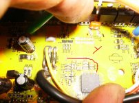
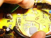
where do I locate the 12v rail/5v rail, I think it is located here but not sure.

1.jpg
2.jpg
3.jpg
4.jpg
5.jpg
6.jpg

Here are some picture of "zombies" modded EB318 controller. I see he has switched out the capacitors for 200v but for the larger ones he is only using 470uf, on my controller they are 1000uf is that ok, why is this? anyone know what the purple caps are?
1.jpg

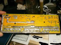
can someone identify the power resistor he is using, the markings on mine have burnt off I've read on chystylte controllers to run 100v you have to have 3 x 1.8k 3 watt resistors, so could I use 1 6k 10watt resistor or 6k 5 watt?. it seems instead of beefing up the traces he instead "beefs" up the tops of the mosfets is this a good strategy? I hope it is ok to use his pictures as I got them off this site

View attachment 6

Thanks for your help so far dnmun it is very much appreciated.
 
I ordered another controller from lyen but this time one rated for 84-132v. I will try to decipher what components have been switched out to make it 100v + compatible, I imagine that it will look similar to zombies controller minus the increased traces on the top of the mosfets, which would make sense since the stock lyen controller can only handle 45A.
 
to find the 12 rail, also known as the 12V supply voltage for the transistors, put the black lead of your voltmeter where it says Grd or VB- since that is the ground for the entire pcb.

use the red probe and look for the 12V on the positive leg of that 20V cap, there will be a trace that runs from the cap over to the 5V regulator, which might read something like LM7805, the 5 regulator will also have one leg attached to the ground trace, another leg on the 12V trace and the third leg is the 5V output.
 
file.php


WOW. Is this a picture of the controller you got from Lyen? looks like someone forgot to finish soldering the traces in to connect 3 of your FETs. So you were really running a 12FET or 15FET in reality.

You need to contact him right now if you bought this controller from him.


The other problem is that you went over the voltage limit. 100v is the literal limit for the FETs and probably the caps.

Yeah, that thing that exploded, that capacitor? thats where i'd start replacing stuff.
 
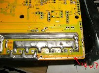
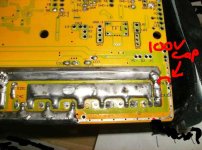
i think that is the high side and it would short to the drains on the low side if there was a connection there. you can see the current coming in on the source next to the C4 label. actually now that i looked again, there is just no need to build up the trace further to the right because there is no current carried from that end.

you don't have to power up the mosfets in order to test the board to see if the microprocessor still works. so those big caps can wait.

but since we don't know if the input voltage regulation works, i thought it would be easiest to attach 12V from a battery, like a 12V SLA, to the 12V rail, and then when the 12V rail is hot, check to see if the 5V regulator works and the 5V rail is hot and then check the microprossesor to see if it works by seeing if it will respond to the hall sensor signals if present by switching the mosfet drivers. but first just try to see if the 5V toggles on the hall sensor leads.
 
dnmun said:
i think that is the high side and it would short to the drains on the low side if there was a connection there. you can see the current coming in on the source next to the C4 label.

you don't have to power up the mosfets in order to test the board to see if the microprocessor still works. so those big caps can wait.

but since we don't know if the input voltage regulation works, i thought it would be easiest to attach 12V from a battery, like a 12V SLA, to the 12V rail, and then when the 12V rail is hot, check to see if the 5V regulator works and the 5V rail is hot and then check the microprossesor to see if it works by seeing if it will respond to the hall sensor signals if present by switching the mosfet drivers. but first just try to see if the 5V toggles on the hall sensor leads.

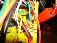
ok so when I put 12v at what I think is the 12v power supply I am getting 5.7v at the hall power wires i.e black and red outputs to motor.


now if this is the 12volt power supply, then when I hooked everything up in the beginning I hit that burned resistor with 100v, it was handling 80v alright but 100 must've been to much. I'm just lucky I didn't fry my cycle analyst at the same time.

so whats the next step... In my impatience I removed all the large caps from the board but will (hopefully) be able to solder them back in
I did not cut them off. I guess the next step is to reattach these and a new power resistor and then power everything up to see if everything switches properly? at a lower voltage of course :oops:

I have a lyen tester so can I use this to check the board?

Edit: it actually feels really good to be learning (in a roundabout/practical sense about these controllers). thank you again for your assistance.
 
neptronix said:
WOW. Is this a picture of the controller you got from Lyen? looks like someone forgot to finish soldering the traces in to connect 3 of your FETs. So you were really running a 12FET or 15FET in reality.

You need to contact him right now if you bought this controller from him.


The other problem is that you went over the voltage limit. 100v is the literal limit for the FETs and probably the caps.

Yeah, that thing that exploded, that capacitor? thats where i'd start replacing stuff.

there is a 100v cap at the c4 junction, it did not blow.

1.1.jpg
 
Yeah maybe because not much in the way of current is traveling through it?

BTW i am wrong about that trace. Apparently it is not filled in on my cell_man 18FET either. It doesn't look like the other controllers i've looked at in the past. The others i've seen have that trace filled in.

Mine would have freaking exploded by now if it was a problem.

I'm sorry for the false alarm :oops:
 
no problem about removing the large caps on the mosfets. the output mosfets are really on a different circuit from the 12V circuit current. the only connection is that the mosfet gate voltage is driven by the mosfet drivers from the 12V rail and it won't make any difference if there is no voltage out there.

it does look like that is the 12V, looks like it runs over to one end of that 3 terminal device Q13, with the ceramic surface mount cap to ground in between, you took out the resistor that bridged from Vcc to the 12V. did you measure the resistor with your voltmeter? don't need it for this anyway.

so connect the 12V battery to the 12V rail and see if you can get 5V outa the 5V regulator which i think i see above the smaller cap above the brown one. that small cap will have 5V across it if the regulator is working. then you gotta connect the hall sensor lead plug to the motor so you can rotate the wheel and get the hall sensor leads to toggle.

then if that works we will look for the traces from the micro out to the mosfet drivers.
 
oh, did not realize you already had the 5V on the hall sensors already. C4 is a high frequency ceramic cap between the source and drain busses.

when you plug in the 5 pin plug to the motor, the red wire, the 5V will provide current to the hall sensor integrated circuit inside the little 3 terminal device we call a hall sensor. which is really a complicated IC. a little complicated. black is ground.

when the magnets move past the hall sensor, they cause the sensor to turn on and turn off sequentially as the magnetic field switches from one pole of the hub magnet to the next. 180o each time.

when the hall sensor is turned on it allows current to flow out of the controller, down the hall sensor lead into the hall sensor, and then through the hall sensor to ground. when it switches off, the current flow stops.

the current for each lead goes through a resistor inside the controller, which you can see right next to where the wires are soldered onto the pcb. 3 in row, GBY leads going out on the other side.

when current from the 5V supply flows through the resistor, there is a voltage drop on the outer end of that resistor as the hall sensor 'sinks' the current to ground. the microprocessor detects this voltage drop and that sets the logic state to the microprocessor as to which of the phases should be active. you can see where the traces run from the end of the resistor back to the micro.

you want to measure the voltage on the outer end of the resistor, just like what the micro sees, as the wheel slowly, i mean slowly, rotates and the magnets move by the hall sensors. verify that all three hall sensors toggle between 5V and almost zero volts. you can also measure this on the wires in the 5 pin plug but since the controller is open just measure right on the trace, with the black probe on grd.

each one has to toggle on and off. when you know that then we can go look for the traces from the micro out to the integrated circuit device that drives the mosfet gates. the driver will be out by each of the mosfets, and the traces will all run together back to the same 3 sequential pins on the micro. gotta find them and then measure the voltages on those traces as you rotate the wheel. the mosfets don't have to be active to do this.

make sense?

edit> just found this circuit richard drew on another thread

http://www.endless-sphere.com/forums/viewtopic.php?f=14&t=36418&p=575114#p575114

i think this is exactly what you have for your input voltage regulation and the Q13 is the 7812, and the diode in the corner is the 20V zener and the resistor connecting them is the little surface mount to the left of the 12V regulator, or maybe it is Q17 for the mosfet and the R120 is the resistor
 
yes that makes sense, thank you. I actually just replaced the hall sensors in the motor so had to learn about them and there function. I will carry out this instruction and report back with my progress.

Thank you so very much

Dfar
 
dnmun said:
the current for each lead goes through a resistor inside the controller, which you can see right next to where the wires are soldered onto the pcb. 3 in row, GBY leads going out on the other side.

when current from the 5V supply flows through the resistor, there is a voltage drop on the outer end of that resistor as the hall sensor 'sinks' the current to ground. the microprocessor detects this voltage drop and that sets the logic state to the microprocessor as to which of the phases should be active. you can see where the traces run from the end of the resistor back to the micro.

you want to measure the voltage on the outer end of the resistor, just like what the micro sees, as the wheel slowly, i mean slowly, rotates and the magnets move by the hall sensors. verify that all three hall sensors toggle between 5V and almost zero volts. you can also measure this on the wires in the 5 pin plug but since the controller is open just measure right on the trace, with the black probe on grd.

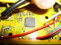
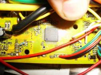
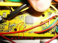
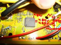
ok so the resistors toggle from near 0v to 5v and I was able to locate (i think) where the traces enter (or exit?) the microprocessor. There was only 3 wires that showed the switching

4.1.jpg
7.1.jpg

dnmun said:
each one has to toggle on and off. when you know that then we can go look for the traces from the micro out to the integrated circuit device that drives the mosfet gates. the driver will be out by each of the mosfets, and the traces will all run together back to the same 3 sequential pins on the micro. gotta find them and then measure the voltages on those traces as you rotate the wheel. the mosfets don't have to be active to do this.

kinda confused about this part I only found 3 leads that switched around the microprocessor as shown above, the others leads only had 0v or 5v.
After looking at the board it becomes obvious that there are 3 repeating units located near the mosfets corresponding to the 3 different phases (i think) and these are connected to independently to the micro processor by single leads. I'm I totally out in left field? I don't know if these are outputs or inputs to the microprocessor.

View attachment 6
8.4.jpg
8.2.jpg
8.31.jpg
8.5.jpg
View attachment 1


dnmun said:
edit> just found this circuit richard drew on another thread

http://www.endless-sphere.com/forums/viewtopic.php?f=14&t=36418&p=575114#p575114

i think this is exactly what you have for your input voltage regulation and the Q13 is the 7812, and the diode in the corner is the 20V zener and the resistor connecting them is the little surface mount to the left of the 12V regulator, or maybe it is Q17 for the mosfet and the R120 is the resistor

I can definitely see the similarity when you point it out but I have no real knowledge of schematics to really be able to verify this one way or the other. It does seem possible that lyen controllers use this type of system as one of the posters of that thread states this seems the case. Also empirically I found the controller could handle any voltage I could throw at it (except obviously one that was too much for the particular resistor). I will have to study more into schematics.

dnmun said:
it does look like that is the 12V, looks like it runs over to one end of that 3 terminal device Q13, with the ceramic surface mount cap to ground in between, you took out the resistor that bridged from Vcc to the 12V. did you measure the resistor with your voltmeter? don't need it for this anyway.

The voltmeter read 1700kohm when I placed the + and - on the traces that the resistor would be attached. The resistor reads nothing, I suspect it has been melted away.

 
wowowow, you did good.

those three traces from the micro are the signal to the mosfet drivers, and if you can see them switch on and off as the wheel turns, you can assume the micro is still functional and you should be able to use the controller again after swapping out the caps and the input resistor. i don't know if those traces will be high or low, but if they change logic state with the hall sensors, then you are home free. really good work to find those so far.

put the black on grd, and red on the three pins on the micro and let us know how it turns out. we can explain about richard's circuit and your input regulation later.
 
dnmun said:
wowowow, you did good.

those three traces from the micro are the signal to the mosfet drivers, and if you can see them switch on and off as the wheel turns, you can assume the micro is still functional and you should be able to use the controller again after swapping out the caps and the input resistor. i don't know if those traces will be high or low, but if they change logic state with the hall sensors, then you are home free. really good work to find those so far.

put the black on grd, and red on the three pins on the micro and let us know how it turns out. we can explain about richard's circuit and your input regulation later.

so I measured the voltage at each trace exiting out the microprocessor and running to the respective mosfets. Each trace measures exactly 4.84v
and does not move when the wheel is turned. I bought a new cap to replace the one that exploded and reconnected all the caps. I replaced the power resistor with a 15k, 5 watt resistor. When I hook everything up to a 80v batt all the caps read 80v however when I plug the input 80v to 12volt line it should turn on the cycle analyst (CA) but doesn't and I have 0 volts at the hall inputs. however when I place 12 volts on the spot I did earlier I get voltage to the halls but no the CA does not turn on and the voltage still does not wavier from 3.84v on the mosfet traces.

3.1.jpg

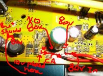
I'm thinking the microprocessor is ok but the problem is with the 80v input to 12v ("80-12v". I checked that connection with the voltmeter when everything was hooked up. I know the "80-12v" is split and one trace converts the 80v to 12v and the other trace is diverted to the cycle annalist to read the voltage of the pack. Perhaps there is another diversion that I can't see that gives the microchip power to toggle the mosfet?


I believe the 100v 100uf cap is blow (although it shows no sign of destruction) because when I tested it with my voltmeter it read 0v across the cap, but 80 v just after the diode. It would make sense that the 80v from the battery would have to go through a 100v 100uf cap and then to a resister and then split, one line going to the Cycle analyst, and one line heading toward the 12v? when I checked the cap with the voltmeter in the resistance setting it show 1 meaning there was no connection ( this I would think would show the cap is dead, the other caps all show near 0 ohm). cold this be my problem? when I went to pick up parts today I did not pick up a 100v 100uf cap only spare 100v 470uf and 160 470uf caps. I'm pretty sure the answer is no but I'll ask anyway, can I use one of the caps I have to see if the board works?

6.3.jpg

I think maybe 'm just grasping at straws now :(
 
well good to grasp at something.

i noticed on the picture where you traced the yellow phase wire section. D0A looks like it blew up and coated the pump up capacitor next to it with debris. is that the case?

not getting a signal on the micro output traces is not good. i expected them to toggle with the wheel since they would need to switch the drivers for the mosfets.

i think that input power resistor woulda been in the 800-1100 ohm range. assuming the controller circuit current is about 60-90milliamps. so it would have about 70V drop across it normally (.060x1100=66V), and i think it is there so that the voltage regulator gets some help in dropping the voltage at the input. some through the 12V regulator and some through the power resistor depending on the voltage at Vcc.

but if that zener diode D0A has blown up that means that the 12V rail got a huge voltage spike that was too much even for that diode. which means the voltages to the mosfet drivers was also very high and they burned up which may have allowed high voltage from the 12V rail through the mosfet driver back to the output of the micro for each of those phases.

there are a lot of smart people here who know a lot more than me about controllers, was hoping they could chime in too, but i am kinda over my head here in how the drivers would work. i assumed the 4.84V would drop to turn the driver off and if they are all on at the same time, that means all three phases are turned on, which never happens normally. usually it is 2 phases on and one off. current goes out of the high side if one phase, through the winding to the connection of the three phase wires in the motor (the wye connection), then back out through the other phase wire, and then drops out through the low side of that phase's mosfets to ground. so only two can be on at one time. so when the micro has all three on all the time, that seems to me to indicate the micro is cooked, along with the mosfet drivers too. and other stuff too i bet. but the 5V regulator is still working. amazing it survived. but maybe the damage to the micro came in through those traces from the mosfet drivers when they got hit with the high voltage on the 12V supply to them. that would account for the huge current surge that blew up the input power resistor too. all jmho. too bad all the smart people have to waste their time monitoring me and what i post up and not helping people with real problems instead of more utube videos of lipo fires.
 
you don't know how much I appreciate your help Dnmun, you've showed me more than your fair share of kindness (or pitty lol). I will continue to tinker away at it, If anything changes I'll let the forum now.
 
hey, that's what we do. we all have burned up controllers, my intro was on duanes golden motor controller when he burned up some parts on it, and then i learned a lot from following richard and dr bass and jeremy and knuckles too. this is how i kinda taught myself some electronics. learning how the BMS works and lifepo4 battery works, and repairing chargers and even graduated to laptops and monitors.
 
ok so a little update.

I talked to lyen and got the correct value of resistor I needed (2W 200 ohm resistor, 72-100v a 300 ohm) but could not find that locally so I bought a 330ohm 5w resistor and replaced that 100v 470uf blown cap, hooked everything up and ....

IT RUNS!!! :mrgreen:

I think before I call it finished and secure it back in it's case I'll try and take some values of what a working controller should show this way I might have an easier time troubleshooting future problems.

This controller will get me through the next couple weeks while I wait for the 134v controller :evil: ... with the new controller I can see the next thing to fry will be the motor :wink:

thanks again dnmun for your help
 
great, i thought it was dead when all those micro outputs read the same thing at the same time. now you know a lot about how the controller works too. never did find out if the pumping diode D0A and the small charge storage cap next to it was blown up like i thought i saw in that picture.
 
dnmun said:
never did find out if the pumping diode D0A and the small charge storage cap next to it was blown up like i thought i saw in that picture.

I think I know what parts you are referring to in which case the diode and 100v 100uf (green cap) were not replaced and everything seems to work fine. they must've been able to handle the high voltage at least until the power resistor failed.
 
Back
Top