Lebowski
10 MW
I decided to start this topic to keep you guys up to date on my controller PCB design and to receive feedback.
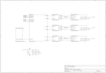
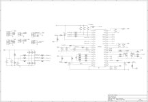
These are the schematics of the controller:
View attachment 5
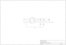
Just some comments about the DCDC converter (the part that generates the 17V and 5V)
The 12F617 has a comparator with on one input a 0.6V reference source and the other input
is alternated between the 17V and 5V feedback signal. When the feedback signal is below
0.6V the 12F turns on the power transistor (via the ncp5181 driver) for 10 u-sec. After a pulse
a certain wait time (dead_time) is observed to prevent astronomical rise of inductor current
on startup. The 10 u-sec is timed by the CCP module for the 5V supply, the 17V uses TMR2
for timing and the pulse is switched off in the interrupt routine.
On startup the 12F waits around 0.5 sec to allow the capacitors around the gate driver to charge fully,
the first 10-usec pulse has to 'hit the money' so it needs a stable 17V from the zener diode pre-charge
before it can produce the first pulse. After startup has completed and the wait-time after each
pulse has been reduced to its minimum the 12F makes the 'power_ready' signal 'high' to turn
on the main controller IC.
The code on the 12F617 (can be used in MPLAB X):
View attachment dcdc_converter.X.zip
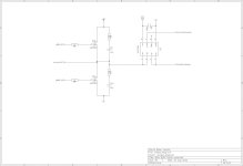
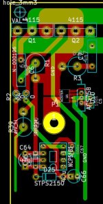
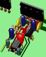
At the moment I'm busy with the gate driver and output stage for 1 motor phase, this is how far I got:
These are the schematics of the controller:


View attachment 5


Just some comments about the DCDC converter (the part that generates the 17V and 5V)
The 12F617 has a comparator with on one input a 0.6V reference source and the other input
is alternated between the 17V and 5V feedback signal. When the feedback signal is below
0.6V the 12F turns on the power transistor (via the ncp5181 driver) for 10 u-sec. After a pulse
a certain wait time (dead_time) is observed to prevent astronomical rise of inductor current
on startup. The 10 u-sec is timed by the CCP module for the 5V supply, the 17V uses TMR2
for timing and the pulse is switched off in the interrupt routine.
On startup the 12F waits around 0.5 sec to allow the capacitors around the gate driver to charge fully,
the first 10-usec pulse has to 'hit the money' so it needs a stable 17V from the zener diode pre-charge
before it can produce the first pulse. After startup has completed and the wait-time after each
pulse has been reduced to its minimum the 12F makes the 'power_ready' signal 'high' to turn
on the main controller IC.
The code on the 12F617 (can be used in MPLAB X):
View attachment dcdc_converter.X.zip
At the moment I'm busy with the gate driver and output stage for 1 motor phase, this is how far I got:


