Lebowski
10 MW
hi 
After strugling for a week I finally got my power controller working. Before I show the schematic, a bit of background. I build my own motor (see other thread)
and my own motor controller. My motor controller does not use the typical PWM to control the output power of the motor. Its a sensorless controller that
turns the 3-wire motor into a 2-wire motor in the same way mechanical commutation would do. The now 2-wire motor is then supplied by the power controller.
The power controller is a boost converter (see wikipedia) which takes the battery voltage and turns it into a higher voltage. It uses one power transistor, the dutycycle
of its gate signal can be used to control the amount of output power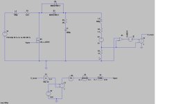
On the top, left to right, first the battery, then the boost converter followed by the motor (600uH, 1.3 Ohm, 40V back EMF) and the current measurement
resistor (0.11 Ohm). This controller controls the motor current, therefore a measurement amplifier (X5) measures the voltage across the current measurement
resistor. The bottom row is a modelled version of the algorithm running in a PIC16F88 processor. It consists of a 10 bit ADC (X1), a voltage source to set the
wanted motor current (V2, 0.07 corresponds to 1 Amp), a 40 Hz loopfilter (X3), a noise-shaper (X4) and the PWM generator (X2). The PWM signal is then
connected to the gate of the power transistor to close the loop.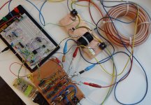
This shows the setup on the workbench. On the breadboard is PIC16F88 with the emergency shutdown circuit (more about that later), the boost converter is
to the right of this with on the far right the inductor (about 10 meters of 6 mm^2 loudspeaker wire, 100uH 30milli-Ohm). The sensorless motor controller is on the
bottom.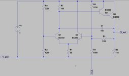
This shows the amplifier that amplifies the voltage from the current measurement resistor. Its a small opamp in feedback, since I didn't have any 5V opamps
lying around I built it with transistors. The gain is 3.3 with a 100 kHz bandwidth. The output is passed through a 100 Hz RC filter (thats somehow missing in the
schematic, sorry ) and is AD converted before ending up at the loopfilter.
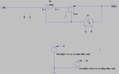
The loopfilter is a simple digital integrator running at 2 kHz clock frequency with a 41Hz unity gain frequency. It has an interesting feature (implemented in X4)
which compensates for the gain dependency of the boost converter. The response of the boost converter to a 1% change in dutycycle is dependent on the dutycycle
it's running at by an amount of 1/(1-duty)^2 with duty from 0 to 1 (for 0 - 100%). So at 50% dutycycle the gain of the boost converter is 4 times what it would
be at 0% dutycycle. Since this can lead to instability this gain dependency is compensated for in X4 by multiplying with (1-duty)^2 (and I can tell you this
is a real b!tch to implement in 16bits when you only have a 8 bits processor )
)
The PIC is running at 8 MHz with a PWM signal at 50 kHz. This means there's only 160 settings of PWM to choose from (8e6/50e3). Since this 'grid' is so coarse simulations
showed the motor current varies by an unacceptable amount when the PWM slowly toggles between 2 values. Therefore the loopfilter is followed by a 1st order
noise-shaper.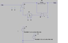
The job of the noise shaper is to toggle the PWM setting at a much higher rate than what the 30Hz loop would be capable of. The noise shaper runs at a 10 kHz clock
(so faster than the 2 kHz clock of the loopfilter) so every 100 usec the PWM setting is changed. The noise shaper is run by an interrupt routine on the 16F88 and
'interrupts' the normal loopfilter routine.
Since the boost converter is a rather dangerous beast an emergency shutdown circuit has been added. When somehow (due to loose connection or something) the
motor would become disconnected the output voltage shoots up to basically unlimited values (the spark plugs in you car are operated by a boost converter) which
would blow up the capacitor and lots of other stuff.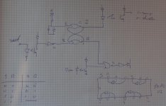
The emergency shutdown uses a zener diode (top left) to detect a voltage higher than about 85 V at which point it trips the Set-Reset flipflop. This then disables
the output stage via the NOR gate at the bottom right. This is then reported back to the PIC (top right bit) which can reset the shutdown circuit (bottom left).
Note that the circuit is configured such that the output transistor is off when the LED's in the optocouplers are off (I did this wrong in the beginning which cost me
a few fuses ).
).
http://www.youtube.com/watch?v=9vGszOvMkeA
I made a youtube video of the actual PWM signal during operation of the controller. The motor (on the bike, the noise is the wheel in the chain-tensioner) is running
and I am varying the amount of braking by putting my foot against the wheel (very scientific, I know ). The power controller is doing its business an tries
to keep the current through the motor at 1 Amp. As the wheel accellerates / decellerates the PWM dutycycle is changed to keep the current at 1 Amp (this also
means the motor voltage changes as a higher motor speed needs more voltage etc).
Since the PIC16F88 has an RS232 module I used this to, while I was recording the scope image, capture the PWM dutycycle.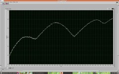
It's a bit 'rough' as I only record the top 8-bits of the 16-bits internal signal. You can see how the dutycycle increases, as the motor speed rises the boost converter needs
a higher dutycycle in order to supply a higher and higher motor voltage (in order to keep current at 1 Amp). As I put my foot in it (to slow the motor down) the dutycycle
decreases again since now less voltage is necessary to maintain 1 Amp motor current.
I know my whole system is different from what's used in the China controllers but for me the fun in this hobby is to try out the more exotic stuff I hope this post
will give you guys some inspiration for your own projects.
P.S. to the moderators: I have no clue why most of the pictures need a click to download while the last one doesn't ? Also no clue how to put the youtube
vid in other than posting the URL ? Can you change this for me please ?
After strugling for a week I finally got my power controller working. Before I show the schematic, a bit of background. I build my own motor (see other thread)
and my own motor controller. My motor controller does not use the typical PWM to control the output power of the motor. Its a sensorless controller that
turns the 3-wire motor into a 2-wire motor in the same way mechanical commutation would do. The now 2-wire motor is then supplied by the power controller.
The power controller is a boost converter (see wikipedia) which takes the battery voltage and turns it into a higher voltage. It uses one power transistor, the dutycycle
of its gate signal can be used to control the amount of output power

On the top, left to right, first the battery, then the boost converter followed by the motor (600uH, 1.3 Ohm, 40V back EMF) and the current measurement
resistor (0.11 Ohm). This controller controls the motor current, therefore a measurement amplifier (X5) measures the voltage across the current measurement
resistor. The bottom row is a modelled version of the algorithm running in a PIC16F88 processor. It consists of a 10 bit ADC (X1), a voltage source to set the
wanted motor current (V2, 0.07 corresponds to 1 Amp), a 40 Hz loopfilter (X3), a noise-shaper (X4) and the PWM generator (X2). The PWM signal is then
connected to the gate of the power transistor to close the loop.

This shows the setup on the workbench. On the breadboard is PIC16F88 with the emergency shutdown circuit (more about that later), the boost converter is
to the right of this with on the far right the inductor (about 10 meters of 6 mm^2 loudspeaker wire, 100uH 30milli-Ohm). The sensorless motor controller is on the
bottom.

This shows the amplifier that amplifies the voltage from the current measurement resistor. Its a small opamp in feedback, since I didn't have any 5V opamps
lying around I built it with transistors. The gain is 3.3 with a 100 kHz bandwidth. The output is passed through a 100 Hz RC filter (thats somehow missing in the
schematic, sorry

The loopfilter is a simple digital integrator running at 2 kHz clock frequency with a 41Hz unity gain frequency. It has an interesting feature (implemented in X4)
which compensates for the gain dependency of the boost converter. The response of the boost converter to a 1% change in dutycycle is dependent on the dutycycle
it's running at by an amount of 1/(1-duty)^2 with duty from 0 to 1 (for 0 - 100%). So at 50% dutycycle the gain of the boost converter is 4 times what it would
be at 0% dutycycle. Since this can lead to instability this gain dependency is compensated for in X4 by multiplying with (1-duty)^2 (and I can tell you this
is a real b!tch to implement in 16bits when you only have a 8 bits processor
The PIC is running at 8 MHz with a PWM signal at 50 kHz. This means there's only 160 settings of PWM to choose from (8e6/50e3). Since this 'grid' is so coarse simulations
showed the motor current varies by an unacceptable amount when the PWM slowly toggles between 2 values. Therefore the loopfilter is followed by a 1st order
noise-shaper.

The job of the noise shaper is to toggle the PWM setting at a much higher rate than what the 30Hz loop would be capable of. The noise shaper runs at a 10 kHz clock
(so faster than the 2 kHz clock of the loopfilter) so every 100 usec the PWM setting is changed. The noise shaper is run by an interrupt routine on the 16F88 and
'interrupts' the normal loopfilter routine.
Since the boost converter is a rather dangerous beast an emergency shutdown circuit has been added. When somehow (due to loose connection or something) the
motor would become disconnected the output voltage shoots up to basically unlimited values (the spark plugs in you car are operated by a boost converter) which
would blow up the capacitor and lots of other stuff.

The emergency shutdown uses a zener diode (top left) to detect a voltage higher than about 85 V at which point it trips the Set-Reset flipflop. This then disables
the output stage via the NOR gate at the bottom right. This is then reported back to the PIC (top right bit) which can reset the shutdown circuit (bottom left).
Note that the circuit is configured such that the output transistor is off when the LED's in the optocouplers are off (I did this wrong in the beginning which cost me
a few fuses
http://www.youtube.com/watch?v=9vGszOvMkeA
I made a youtube video of the actual PWM signal during operation of the controller. The motor (on the bike, the noise is the wheel in the chain-tensioner) is running
and I am varying the amount of braking by putting my foot against the wheel (very scientific, I know
to keep the current through the motor at 1 Amp. As the wheel accellerates / decellerates the PWM dutycycle is changed to keep the current at 1 Amp (this also
means the motor voltage changes as a higher motor speed needs more voltage etc).
Since the PIC16F88 has an RS232 module I used this to, while I was recording the scope image, capture the PWM dutycycle.

It's a bit 'rough' as I only record the top 8-bits of the 16-bits internal signal. You can see how the dutycycle increases, as the motor speed rises the boost converter needs
a higher dutycycle in order to supply a higher and higher motor voltage (in order to keep current at 1 Amp). As I put my foot in it (to slow the motor down) the dutycycle
decreases again since now less voltage is necessary to maintain 1 Amp motor current.
I know my whole system is different from what's used in the China controllers but for me the fun in this hobby is to try out the more exotic stuff
will give you guys some inspiration for your own projects.
P.S. to the moderators: I have no clue why most of the pictures need a click to download while the last one doesn't ? Also no clue how to put the youtube
vid in other than posting the URL ?

