RWP
1 kW
Cortina Triton DS - My first electric bicycle.

I am in awe over all the fine work that is coming out of ES.
All this is soooooooo inspirational for me. In a way it has changed my life and changed my direction.
So my hat’s off to Matt and all of you creative hard working pioneers!!!
About a year ago I saw Matt’s build site for the recumbent and flipped out - it was so very cool. I wanted one. Many years ago I worked on cars but somehow never got into making custom stuff, but it was always on my mind. Since then I had a number of professional type design oriented and Internet based carriers. Recently I longed to work with my hands again, sitting in front of a computer day in and day out was getting really old. Seeing all this creativity blasted me into action.
My goals are many and I have a number of reasons for wanting to make electric bicycles:
One is simply to make an attractive, powerful, and practical electric bike and in the future three-wheeled, two seat, full suspension electric vehicles.
I want to provide a real alternative to fossil fuel vehicles.
I want to demonstrate and encourage others that with relatively simple tools and some dedicated time and energy and a bit of ingenuity one can make an electric bike in a garage.
I want to re-skill myself to work with more advanced tools and processes like bench top milling machines and engine lathes.
I started making sketches of drive units similar to Matt’s that became known as Phase 1. Then I got a bike to power up. It’s a hard tail Cortina and my first build is with what I call the Phase 2 guts enclosed motor drive unit.
A little back story: About a year ago I met a friend who also was interested in electric vehicles. We both wanted to do a car conversion but held back because of the cost of batteries and the shear size of the project. We started talking and decided to do an electric motorcycle conversion project - a 250 Ninja.
So many words so little time…one thing led to another and in January in earnest we started on the Ninja and two other projects. My friends project was to put e-power to a BOB bicycle trailer and mine was to power the Cortina. In order to keep us on track we set a goal to have all three projects in running presentable form to show at Earth Day here in Santa Barbara. We did it!!!
The deadline kept us focused and on track. All the projects work but as can be expected with prototypes and home builds they need further development and fine-tuning. It was a great high to get all this together in 4 months; we started in earnest in January. Earth Day was April 19th.
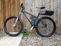
OK, on to the Cortina
It’s a Cortina Triton DS (http://en.wikipedia.org/wiki/Cortina_Cycles) with a Towerpro motor, HV110 controller and Lipo’s. Elsewhere in ES several people mentioned that it would be cool to have the drive reduction components inside and not exposed. This got me thinking about how I might enclose the pulleys and belts. The solution I chose was to put the drive unit reduction parts inside 2â€Âx4â€Âx1/8†alu tubes. I went with these tubes because I could buy them off the shelf and modify them as needed. There were issues with this choice but to get going it was the decision I made. The Phase 3 drive will be much easier to work with.
View attachment 1

Enclosed 5mm GT2 x 15mm drive unit ratios:
15 – 56 primary belt drive – Motor to Jackshaft - enclosed
20 (was 15) – 56 secondary belt drive – Jackshaft to Output shaft – enclosed
Exposed BMX Chain ratios:
16 – 48 primary BMX chain – Output shaft freewheel to Crank Chainring
30 – 18 secondary BMX chain - Crank to Nexus Inter3 w/disk brake hub
…then the ratios in the hub…still trying to find out what they are…
I can pedal to about 20mph and then the motor over runs the cranks. So far I have pushed it to 34mph with more throttle to twist.
The bike weighs about 52 lbs.
One of the ideas kicked around in ES was to enclose the drive system. Seems I remember a few posts about this. I went with 2â€Âx4â€Âx1/8†aluminum tubing. One for the primary drive and another for the secondary drive. The bearings have split rings in the outer races and are installed from the inside. I think they look cool in contrast to the anodized aluminum tubing. The 2x4 tubing restricted the reduction ratio because the largest pulley/belt I could get into the 4†dim was 56 teeth. Mostly it’s been successful but it’s a bear to work on because everything seems to be connected to everything else. Pulleys and spacers hold the bearings in place and it’s all very cramped – it goes together a bit like a puzzle. In this way Matt’s drives are the ultimate in simplicity. Phase 2 is OK for a prototype but the Phase 3 drive will be much more user friendly. The only reason I did not go with Matt's drive was that all the spinning stuff is exposed. Again this is not a criticism of this drive which I perceive as very prototype and development friendly. My preference is not to have any spinning stuff exposed including the motor.
The jackshaft and final drive shaft are ½â€ mild steel (if mild steel is not the best material for this use - suggestions are appreciated) from McMaster and now that I have my X3 Small Mill going and machined flats on the shafts they are much easier to work with. Previously I made the flats with a file…
Another thing I did was to use two belts instead of a belt and chain. Time will tell if this will work. So far so good but the Towerpro motor is rated at about 2700 watts (I cannot verify this rating) and if I go to a larger motor the secondary belt may fail.
The original 15x56 secondary drive belt failed. Made awful sounds that I finally traced to the belt jumping cogs. Went to a 20x56 (from 15x56) and still have to test it to be sure it will work in the long run. This gave me 8 instead of 6 teeth engaged on the drive pulley. So far so good, but I have not yet really cranked on the power fully.
I went looking for 8mm pitch pulleys and belts and came up more or less empty. Torquetrans.com http://www.torquetrans.com/pulleys/timing-pulleys/8mm.htm, which seems to have all the right stuff, will not sell individual pieces like Stock Drive. Perhaps I am missing something here but I think the 8mm pitch x 20mm wide belt systems will take all the punishment we can give it. I think the belts are readily available, it’s the pulleys that are hard to find and when they can be found are very dear. Another way must be found to attach the pulleys to the shafts as my grub screws all seem to loosen over time. I also do not think grub screws were designed to handle the torque I will be putting to them.
I read about people using internal geared hubs and wanted to give this a try. Shimano recently came out with a three-speed hub with disk brake and it worked just fine lining up with the existing caliper without any modification. Used a Surly chain tensioner to take up the slack. The rotating shift mechanism is mounted on the left handlebar - so I am free to twist the throttle with my right hand and shift with my left.
It’s a through the crank drive and this was a bit fun to put together. Thanks again to ES and you guys…ES is everywhere in this project – so if I forgot to give credit I give blanket credit here. I got the crank and freewheel stuff from Sick Bike Parts and the offset BB from TartyBikes. I started with a standard Shimano BB but the inner chain ring was too close to the chain stay…then got an Echo offset BB that give me a few extra mm’s for clearance. I think it still rubs a bit when pedaling hard.

OK, looks like the Sick Bike Parts trials White Industry freewheel adaptor has a lot of side to side play. Not sure exactly how much but it seems significant – way more than I am comfortable with. It has not failed but then I have not really ridden it enough to tell how it will hold up over time.
I was trashing drive output freewheels until I put an ENO on. Now all is well.
The batts are Lipo’s in 10s2p configuration (four - 5s 5000mAh - Zippy Flightmax 20c) – 36 volts @ 10 amp/hr. They are housed in a sturdy plastic case along with a contactor and main disconnect. The case is mounted on a seat post rack. I hope in the near future to double up the pack to 20 amp/hrs.
The throttle control is via Magura wired into the servo tester replacing the pot. There is a kill switch as well. I start by switching on the disconnect and when I hit the kill switch the contactor closes and the controller fires up. I also have an eLogger in the system. For now the HV110, servo tester, BEC and logger sit on a Lexan board in front of the battery case. I am planning to make a box for this stuff something like oofnik did for his Mongoose DX build. So far I have not pulled more than about 60 amps, but I am being gentle because of the belt situation.

I have been thinking about going to a larger motor because the Towerpro runs hot. Not sure what the actual temp is but at times it’s too hot to keep my hand on. Now that the drive unit issues seem to be resolved I will run it for a while and see what happens with the temp and power. I am concerned that if I go to a larger motor the belt slipping issue will return. So for now I will wait and see how it goes.
Not sure just where and how to add caps to the controller. I got 2 - 50v 1000mf caps and wired them onto a Dean connector (the polarity is correct). I made a Dean connector adaptor to allow an inline installation but this puts the caps about 4 or 5 inches from the HV110 and the caps are soldered to the adaptor with 2 to 3 inch leads. I am a little gun shy because when I first tried to add the caps I fried a BEC. Truth is I may have had the BEC installed with the polarity reversed.
I will soon have more info from the logger and will post that here.
Mounting…seems like tremendous energy is going towards developing a clamping system that does not alter the bike (an observation not a criticism)…I decided to alter the frame to mount the drive unit. I drilled two holes in the seat tube and brazed threaded sleeves into these holes. A U shaped alu mount screws into the 2x4 secondary drive tube and is slotted to fit the sleeves brazed onto the frame. The slots allow the motor unit to slide up and down to tension the drive to BB chain.
I put Bontrager Hank 2.2 slick tires front and back for a cool look and fine ride. I wanted to get another pair but seems I got the last ones available in Santa Barbara!
Speaking of riding…this thing flies…still working out some driveline/freewheel issues (seems going from 15 to 20 tooth pulley and the ENO has made a big difference) so I have not twisted to full power. But it pulls strong in second and third gear and it feels like it may wheelie in first. It will start from a stop in third gear just fine but I have been pedaling in first and then screwing on the throttle then easing off the throttle to up shift. I can pedal normally in all three gears and when the electric kicks in it just pulls away overrunning the pedals. So far CatEye tells me the Cortina goes 34mph with more left in the throttle.
My main problem areas have been the slipping secondary belt and going through freewheels. I think the freewheel issue is solved and, unless I can find some 8mm pulleys and belts, I will most likely to go to a chain for anything over the first reduction in the future.
I do not know if the secondary belt drive unit, motor or internal 3-speed hub will hold up over time. This is still to be determined.
I want to revisit my original goals and see if I have achieved what I wanted in my first electric bike project.
Failures:
Hard to access the drive unit internals for easy repair
5mm timing belts do not seem up to the torque after the first drive reduction (I know – I know – this was made very clear)
Motor runs hot (is probably too small for my design goals
Up for Grabs:
Through the crank drive – seems fussy to gear the drive down and then back up again at the crank
Fixed center design for the secondary belt (no tensioning system)
3-speed hub –do not know if it will handle the power but so far so good
Every time I take the drive unit apart I check for, and find, loose grub screws. Perhaps another way can be found to secure the pulleys and sprockets to the shafts?
Lipo battery
Successes:
Building this bike has been great fun and a personally rewarding experience
I built my first running eBike with relatively simple tools and some outside machine shop work
It’s an attractive machine that goes faster than I am comfortable riding
It’s a great test bed for future projects
Easy to remove drive unit from bike
Wishes for the future:
Enclosed transmission of some type (CV would be great) – maybe with a 90-degree drive system
Purpose made controllers
Better range of quality motors
Battery – love to find a non volatile battery with equal or greater energy density
Again much appreciation to all the great folks and projects here on Endless-Sphere.
I know this is a monster post...I shall try to restrain myself in the future. If you have gotten this far - THANK YOU!
Roy
I am in awe over all the fine work that is coming out of ES.
All this is soooooooo inspirational for me. In a way it has changed my life and changed my direction.
So my hat’s off to Matt and all of you creative hard working pioneers!!!
About a year ago I saw Matt’s build site for the recumbent and flipped out - it was so very cool. I wanted one. Many years ago I worked on cars but somehow never got into making custom stuff, but it was always on my mind. Since then I had a number of professional type design oriented and Internet based carriers. Recently I longed to work with my hands again, sitting in front of a computer day in and day out was getting really old. Seeing all this creativity blasted me into action.
My goals are many and I have a number of reasons for wanting to make electric bicycles:
One is simply to make an attractive, powerful, and practical electric bike and in the future three-wheeled, two seat, full suspension electric vehicles.
I want to provide a real alternative to fossil fuel vehicles.
I want to demonstrate and encourage others that with relatively simple tools and some dedicated time and energy and a bit of ingenuity one can make an electric bike in a garage.
I want to re-skill myself to work with more advanced tools and processes like bench top milling machines and engine lathes.
I started making sketches of drive units similar to Matt’s that became known as Phase 1. Then I got a bike to power up. It’s a hard tail Cortina and my first build is with what I call the Phase 2 guts enclosed motor drive unit.
A little back story: About a year ago I met a friend who also was interested in electric vehicles. We both wanted to do a car conversion but held back because of the cost of batteries and the shear size of the project. We started talking and decided to do an electric motorcycle conversion project - a 250 Ninja.
So many words so little time…one thing led to another and in January in earnest we started on the Ninja and two other projects. My friends project was to put e-power to a BOB bicycle trailer and mine was to power the Cortina. In order to keep us on track we set a goal to have all three projects in running presentable form to show at Earth Day here in Santa Barbara. We did it!!!
The deadline kept us focused and on track. All the projects work but as can be expected with prototypes and home builds they need further development and fine-tuning. It was a great high to get all this together in 4 months; we started in earnest in January. Earth Day was April 19th.
OK, on to the Cortina
It’s a Cortina Triton DS (http://en.wikipedia.org/wiki/Cortina_Cycles) with a Towerpro motor, HV110 controller and Lipo’s. Elsewhere in ES several people mentioned that it would be cool to have the drive reduction components inside and not exposed. This got me thinking about how I might enclose the pulleys and belts. The solution I chose was to put the drive unit reduction parts inside 2â€Âx4â€Âx1/8†alu tubes. I went with these tubes because I could buy them off the shelf and modify them as needed. There were issues with this choice but to get going it was the decision I made. The Phase 3 drive will be much easier to work with.
View attachment 1
Enclosed 5mm GT2 x 15mm drive unit ratios:
15 – 56 primary belt drive – Motor to Jackshaft - enclosed
20 (was 15) – 56 secondary belt drive – Jackshaft to Output shaft – enclosed
Exposed BMX Chain ratios:
16 – 48 primary BMX chain – Output shaft freewheel to Crank Chainring
30 – 18 secondary BMX chain - Crank to Nexus Inter3 w/disk brake hub
…then the ratios in the hub…still trying to find out what they are…
I can pedal to about 20mph and then the motor over runs the cranks. So far I have pushed it to 34mph with more throttle to twist.
The bike weighs about 52 lbs.
One of the ideas kicked around in ES was to enclose the drive system. Seems I remember a few posts about this. I went with 2â€Âx4â€Âx1/8†aluminum tubing. One for the primary drive and another for the secondary drive. The bearings have split rings in the outer races and are installed from the inside. I think they look cool in contrast to the anodized aluminum tubing. The 2x4 tubing restricted the reduction ratio because the largest pulley/belt I could get into the 4†dim was 56 teeth. Mostly it’s been successful but it’s a bear to work on because everything seems to be connected to everything else. Pulleys and spacers hold the bearings in place and it’s all very cramped – it goes together a bit like a puzzle. In this way Matt’s drives are the ultimate in simplicity. Phase 2 is OK for a prototype but the Phase 3 drive will be much more user friendly. The only reason I did not go with Matt's drive was that all the spinning stuff is exposed. Again this is not a criticism of this drive which I perceive as very prototype and development friendly. My preference is not to have any spinning stuff exposed including the motor.
The jackshaft and final drive shaft are ½â€ mild steel (if mild steel is not the best material for this use - suggestions are appreciated) from McMaster and now that I have my X3 Small Mill going and machined flats on the shafts they are much easier to work with. Previously I made the flats with a file…
Another thing I did was to use two belts instead of a belt and chain. Time will tell if this will work. So far so good but the Towerpro motor is rated at about 2700 watts (I cannot verify this rating) and if I go to a larger motor the secondary belt may fail.
The original 15x56 secondary drive belt failed. Made awful sounds that I finally traced to the belt jumping cogs. Went to a 20x56 (from 15x56) and still have to test it to be sure it will work in the long run. This gave me 8 instead of 6 teeth engaged on the drive pulley. So far so good, but I have not yet really cranked on the power fully.
I went looking for 8mm pitch pulleys and belts and came up more or less empty. Torquetrans.com http://www.torquetrans.com/pulleys/timing-pulleys/8mm.htm, which seems to have all the right stuff, will not sell individual pieces like Stock Drive. Perhaps I am missing something here but I think the 8mm pitch x 20mm wide belt systems will take all the punishment we can give it. I think the belts are readily available, it’s the pulleys that are hard to find and when they can be found are very dear. Another way must be found to attach the pulleys to the shafts as my grub screws all seem to loosen over time. I also do not think grub screws were designed to handle the torque I will be putting to them.
I read about people using internal geared hubs and wanted to give this a try. Shimano recently came out with a three-speed hub with disk brake and it worked just fine lining up with the existing caliper without any modification. Used a Surly chain tensioner to take up the slack. The rotating shift mechanism is mounted on the left handlebar - so I am free to twist the throttle with my right hand and shift with my left.
It’s a through the crank drive and this was a bit fun to put together. Thanks again to ES and you guys…ES is everywhere in this project – so if I forgot to give credit I give blanket credit here. I got the crank and freewheel stuff from Sick Bike Parts and the offset BB from TartyBikes. I started with a standard Shimano BB but the inner chain ring was too close to the chain stay…then got an Echo offset BB that give me a few extra mm’s for clearance. I think it still rubs a bit when pedaling hard.
OK, looks like the Sick Bike Parts trials White Industry freewheel adaptor has a lot of side to side play. Not sure exactly how much but it seems significant – way more than I am comfortable with. It has not failed but then I have not really ridden it enough to tell how it will hold up over time.
I was trashing drive output freewheels until I put an ENO on. Now all is well.
The batts are Lipo’s in 10s2p configuration (four - 5s 5000mAh - Zippy Flightmax 20c) – 36 volts @ 10 amp/hr. They are housed in a sturdy plastic case along with a contactor and main disconnect. The case is mounted on a seat post rack. I hope in the near future to double up the pack to 20 amp/hrs.
The throttle control is via Magura wired into the servo tester replacing the pot. There is a kill switch as well. I start by switching on the disconnect and when I hit the kill switch the contactor closes and the controller fires up. I also have an eLogger in the system. For now the HV110, servo tester, BEC and logger sit on a Lexan board in front of the battery case. I am planning to make a box for this stuff something like oofnik did for his Mongoose DX build. So far I have not pulled more than about 60 amps, but I am being gentle because of the belt situation.
I have been thinking about going to a larger motor because the Towerpro runs hot. Not sure what the actual temp is but at times it’s too hot to keep my hand on. Now that the drive unit issues seem to be resolved I will run it for a while and see what happens with the temp and power. I am concerned that if I go to a larger motor the belt slipping issue will return. So for now I will wait and see how it goes.
Not sure just where and how to add caps to the controller. I got 2 - 50v 1000mf caps and wired them onto a Dean connector (the polarity is correct). I made a Dean connector adaptor to allow an inline installation but this puts the caps about 4 or 5 inches from the HV110 and the caps are soldered to the adaptor with 2 to 3 inch leads. I am a little gun shy because when I first tried to add the caps I fried a BEC. Truth is I may have had the BEC installed with the polarity reversed.
I will soon have more info from the logger and will post that here.
Mounting…seems like tremendous energy is going towards developing a clamping system that does not alter the bike (an observation not a criticism)…I decided to alter the frame to mount the drive unit. I drilled two holes in the seat tube and brazed threaded sleeves into these holes. A U shaped alu mount screws into the 2x4 secondary drive tube and is slotted to fit the sleeves brazed onto the frame. The slots allow the motor unit to slide up and down to tension the drive to BB chain.
I put Bontrager Hank 2.2 slick tires front and back for a cool look and fine ride. I wanted to get another pair but seems I got the last ones available in Santa Barbara!
Speaking of riding…this thing flies…still working out some driveline/freewheel issues (seems going from 15 to 20 tooth pulley and the ENO has made a big difference) so I have not twisted to full power. But it pulls strong in second and third gear and it feels like it may wheelie in first. It will start from a stop in third gear just fine but I have been pedaling in first and then screwing on the throttle then easing off the throttle to up shift. I can pedal normally in all three gears and when the electric kicks in it just pulls away overrunning the pedals. So far CatEye tells me the Cortina goes 34mph with more left in the throttle.
My main problem areas have been the slipping secondary belt and going through freewheels. I think the freewheel issue is solved and, unless I can find some 8mm pulleys and belts, I will most likely to go to a chain for anything over the first reduction in the future.
I do not know if the secondary belt drive unit, motor or internal 3-speed hub will hold up over time. This is still to be determined.
I want to revisit my original goals and see if I have achieved what I wanted in my first electric bike project.
Failures:
Hard to access the drive unit internals for easy repair
5mm timing belts do not seem up to the torque after the first drive reduction (I know – I know – this was made very clear)
Motor runs hot (is probably too small for my design goals
Up for Grabs:
Through the crank drive – seems fussy to gear the drive down and then back up again at the crank
Fixed center design for the secondary belt (no tensioning system)
3-speed hub –do not know if it will handle the power but so far so good
Every time I take the drive unit apart I check for, and find, loose grub screws. Perhaps another way can be found to secure the pulleys and sprockets to the shafts?
Lipo battery
Successes:
Building this bike has been great fun and a personally rewarding experience
I built my first running eBike with relatively simple tools and some outside machine shop work
It’s an attractive machine that goes faster than I am comfortable riding
It’s a great test bed for future projects
Easy to remove drive unit from bike
Wishes for the future:
Enclosed transmission of some type (CV would be great) – maybe with a 90-degree drive system
Purpose made controllers
Better range of quality motors
Battery – love to find a non volatile battery with equal or greater energy density
Again much appreciation to all the great folks and projects here on Endless-Sphere.
I know this is a monster post...I shall try to restrain myself in the future. If you have gotten this far - THANK YOU!
Roy