crossbreak
1 MW
yes! maddin got it!

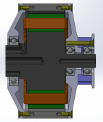
minimum said:1. IMHO there's not enough room between bearing seat (I'm not sure the exact term in English) and holes/threads for screws. Very thin wall tends to end up be torn or distorted during machining.
2. Unless the rim for timing pulley is a separate part, how do you install the outer bearing?

 )
)*fixedmacribs said:Video not viewable.
larsb said:I agree with above from minimum, wall thickness is too low towards bearing seat. I drilled out my revolt motor to fit 8awg wire and the surface buckled towards bearing side due to too thin walls. I think the drilling operation might be better done first and turning later as drilling creates more forces on the material than the turning (depending of cut depth
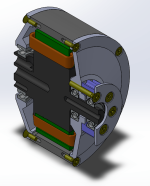
i know revolt and turnigy do it this way. I had broken strands on the cable exit once or twice, which is hard to fix if you are in the field without striping the whole motor. something you defnitly dont want. hubmotors have those connections inside, my design is more like a hubmotor, so id like it to be that way, too. I think the extra effort is worth it, as long it does not add axial length to the overall designJohn in CR said:I've found the easiest way to get the most copper out of the axle is using magnet wire, so instead of three sets of phase wires each with insulation all of the phases can be combined in one bundle (along with the hall sensor and temperature wires) for more copper but using multiple layers ending up with more insulation protection. There's no need for flexibility until outside, so I'd suggest leaving extra length when winding and just bring the phase windings outside of the motor.
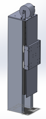
thx but they have no PolyChain pattern. A HTD M8 belt would be too wide to fit the buildspace. I know a polychain/DeltaChain is expensive ($50+ for a 150T, 12mm wide 8M belt) but it's the best you can buy for the purpose, and i should last ~10.000 milesminimum said:
crossbreak said:thx, i'll try it that way. And thicken the wall, ATM it is .8mm which might be too athletic i agree. i'll try making it >1mm by shifting the BCD by .5mm (bolt circle diameter)
dont worry if you dont find the belt in those pics, it's still missing in the model but it will go on as soon as the temperature in the workshop drops. Good news: There will be a better lathe soon, i'll get it from an old gunsmith, it is more precise than the chinese thing i got recently.