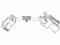
Crystalyte 36v-72v 35a controller throttle color code

Joined
Jun 12, 2008
Messages
76
Location
England
I have started putting my Crystalyte 36v-72v 35a controller on my bike but am not getting any feed back from my hub motor on stripping back the heat shrink of the throttle connector on the controller there is a red,orange,yellow,and white wire, my crystalyte brand 3 pin thumb throttle has 3 wires red green yellow dose anyone no which wires go to which.
The connetors fit together with the
red to red
orange to green
yellow to yellow
white to blank
 
aaannndddyyy said:
I have started putting my Crystalyte 36v-72v 35a controller on my bike but am not getting any feed back from my hub motor on stripping back the heat shrink of the throttle connector on the controller there is a red,orange,yellow,and white wire, my crystalyte brand 3 pin thumb throttle has 3 wires red green yellow dose anyone no which wires go to which.
The connetors fit together with the
red to red
orange to green
yellow to yellow
white to blank

How you have it listed is correct.

-- Gary
 
GGoodrum said:
How you have it listed is correct.

-- Gary

Thanks Gary
I have spent the day reading the forum and testing all the wires. ie hall,phase wires,battery wires,tried the 36 combinations, tried 2 different throttles, to different motors (Ezee + 5304), still no response. the Cycle Analyst shows all normal, the power light on the controller stay on with no flashes.
The only thing that seems out is
When I tested the voltage on the throttles it shows
Red + green - = 4.5volts
Red + yellow - = 3.2volts
Green - yellow + 1volt
These numbers dont change whatever the position the throttle is in?.
 
over the years i have seen darn near evry color of the rainbow used in those wires. and what was right at one time will be wrong farther down the road.

there is no consistency in these colors. there is no color code. Kenny's (kenny owns crystalyte) nephew who does these connectors is color blind. even if the cable has the same color wires it does not mean it is still connected order or sequence. that is why none of the suppliers list the wire colors. what is important is the position of the wire in the connector.

what gary said about the colors may be true for the units he has on hand. likely they will not work on older or newer throttles. or they might keep the order of the colors the same for a while. no guarantees.

if you still have the connectors handy here are the pinouts
Rectangular-3-Pin-Connector.gif


if you experimented with the wires by mixing and matching it is almost certain that you have destroyed the hall sensor element.

rick
 
rkosiorek said:
over the years i have seen darn near evry color of the rainbow used in those wires. and what was right at one time will be wrong farther down the road.

there is no consistency in these colors. there is no color code. Kenny's (kenny owns crystalyte) nephew who does these connectors is color blind. even if the cable has the same color wires it does not mean it is still connected order or sequence. that is why none of the suppliers list the wire colors. what is important is the position of the wire in the connector.

if you experimented with the wires by mixing and matching it is almost certain that you have destroyed the hall sensor element.

rick
No haven’t done that yet just tested with volt meter.
After going though 4 ecrazyman controllers in a year a half all needing some modifications to work. Decided if I bought a controller, throttle, and motor made by the same company they might be compatible with each other, hobbies can be very frustrating sometimes.

One of the most important lessons I have learnt here is to have at least 2 electric bikes, one to ride well upgrading modifying and repairing the other. No matter how frustrating it gets there’s nothing like getting on an electric bike and going around the city not having to worry about traffic jams, red lights,spot fines,camaras,petrol costs,ect and it allways puts a smile on my face doing 30+mph on a ebike.
This forum has been invaluable in keeping me sane and on the road over the last 2 years, keep up the good work.
 
the +5V wire goes to pin #1 of these connectors. pin #2 is the GND or 0V and pin #3 is the signal. pin #4 goes straight to the battery (+) and is used for the little LED battery meter some of these have built in. if you have the throttle plugged in and you probe the connections to test if it is working. at rest you should read 0.7 ~ 1.0V between the signal and GND (pin 2 and pin 3) as you advance the throttle the voltage should go up to 4.2 ~ 4.5V at max throttle. if it does not than something is wrong with the throttle.

if the throttle puts out the right signal it should work. if it does not, then disconnect the E-Brake levers if you have them. those things are notorious for getting stuck in the "ON" position and the motor will not turn. disconnecting them will identify that issue.

last. check all of the pins in those little flat plastic connectors used for the throttle, brakes, Cycle-Analyst etc. they can be tricky to assemble. occasionally the pins are not firmly seated in place and when you plugged them together the pin is pushed back into the housing and does not make a good connection. rarer still the pins were improperly crimped and do not make a good connection. to check that get a small pin. push that through the wire insulation about 1/2" back and test for continuity at the tip of the connector.

does. it do anything? buzz? Jump? or does it just sit there like a lump?

rick

i just checked a couple of the 3 wire throttles i have here. one has red, yellow, black with the yellow as GND and the Black as the signal wire. 2 others are red, white and green. all of them use the red as the +5. though i am pretty sure that is only a co-incidence.
 
Thanks for your help Gary and Rick.
I have power going to the wheel at last :D ; pins 2 and 3 on the controllers throttle connector have been wired up backwards, I am not an electrician and didn’t what to start mixing and matching without some professional advice first.
The color code worked out to be
Controller motor
Red to red
Orange to yellow or black depending which throttle I’m using,
Yellow to green
Now it’s just a matter of sorting out hall and phase wire combinations which I have done so often it’s become second nature.
Thanks again.
 
now justin at e-bikes.ca is starting up a new can of worms. well, not really, but sorta, maybe....

he wants to standardise all of the connectors he uses across all of the motors and controllers that he stocks. the throttle and brake ones are okay as it seems that most use the same pattern. but the hall sensor connector is different. all will use the same flat black pastic connector. but he will rewire all of the motors and controllers to use the pin out used by the eZee motor kits.

the confussion will come for those that buy a new Crystalyte controller that will use the same black plastic hall sensor connector as the old one to replace his old unit (the connectors look the same) and now it won't work because the hall wiring is different. i'll bet we'll see a lot more of those "Why Won't My New Crystalyte..."

rick
 
The Crystalyte Controller 36-72V 35A and the 5304 hall and phase wires match so no combination to mess around with :)
Not so with my Ezee fw motors these motors are off a company called 50Cycles that sold there old stock last year they come off the Ezee sprint electric bikes.
Tried all 36 combos on a used motor not one worked, so tried on a new motor (I have three) still no luck the only color that gave any forward motion was color matching at low speed all seemed good on both motors but get above 25% throttle they become erratic sounds like its works for about 2/3 of a revolution then no power for a 1/3.
Had similar problem with all the Ecrazyman controllers I tried, fixed the problems for a while by changing 16mhz resonator for a 24 MHz on one worked for a while then started playing up, that’s when I went for the Ecrazyman censorless controller more problems, by taking the sensorless board out and wiring up as a normal censored worked for a while (6 months) and then started playing up, sometimes worked fine then jumps and judders with no forward motion disconnecting the battery for a few hours will work for a while sometime a day or two then back to juddering these motors must be wired differently stressing the controllers till they brake down, not going to waste any more time or cash on them.
 
Back
Top