
You are using an out of date browser. It may not display this or other websites correctly.
You should upgrade or use an alternative browser.
You should upgrade or use an alternative browser.
Current limiting resistor vs Charging with CC-CV the true!
- Thread starter Doctorbass
- Start date

safe
1 GW
- Joined
- Dec 22, 2006
- Messages
- 5,681
Circuit Designs Wanted!
 Forget About Balancing.
Forget About LVC. (Low Voltage Cutoff)
Simply and narrowly address the issue of a SINGLE cell being charged by a SINGLE power supply. How does one create a circuit that would be able to handle a high voltage limit of 4.25 volts and something like 13 Amps of power for a Thundersky cell? (about 65 Watts)
And make sure the circuit is CC-CV and NOT resistor based.

This was the power supply I had in mind:
http://www.mpja.com/prodinfo.asp?number=12922+PS
5V * 13A = 65W.
$8.95 for 10 or more.
Simply and narrowly address the issue of a SINGLE cell being charged by a SINGLE power supply. How does one create a circuit that would be able to handle a high voltage limit of 4.25 volts and something like 13 Amps of power for a Thundersky cell? (about 65 Watts)
And make sure the circuit is CC-CV and NOT resistor based.
This was the power supply I had in mind:
http://www.mpja.com/prodinfo.asp?number=12922+PS
5V * 13A = 65W.
$8.95 for 10 or more.
dirty_d
10 kW
safe, like with the circuit i posted in my lipo thead, you don't even have to look at the balancing stuff, just the cc/vc schematic. if you use the fets like in a motor controller and give a a good heatsink you could do the high current.
this schematic does exactly as you just said it does the CC/CV charging, http://endless-sphere.com/forums/download/file.php?id=7390
you would just change 20V main supply to soemthing like 5V and where it shows the 12.6V lipo pack that would be your single 4.2V cell. you still need about 15V though for the FET gate. the lowesr op-amp and everything connected to it wouldn't be needed either.
safe
1 GW
- Joined
- Dec 22, 2006
- Messages
- 5,681
Even Better?
Power Supply ($8.95)
4.2 Voltage Detector ($0.76)
http://digikey.com/scripts/DkSearch/dksus.dll?Detail?name=BD45421G-CT-ND
MOSFET ($1.73)
http://digikey.com/scripts/DkSearch/dksus.dll?Detail?name=2SK2401TE24LQCT-ND
Final Totals:
$11.44 for 65W - 5V @ 13A Single Cell Charger
17.6 cents per Watt
...but how do I get the needed 10V gate voltage?
One of the advantages of using the computer power supplies is that you should be able to draw from BOTH the 5V power and from the 12V power, so MOSFET gate driving is as easy as plugging it in. Without it you would need to provide a gate driver power supply which increases the cost.
http://digikey.com/scripts/DkSearch/dksus.dll?Detail?name=BD45421G-CT-ND
http://digikey.com/scripts/DkSearch/dksus.dll?Detail?name=2SK2401TE24LQCT-ND
Final Totals:
$11.44 for 65W - 5V @ 13A Single Cell Charger
17.6 cents per Watt
...but how do I get the needed 10V gate voltage?
One of the advantages of using the computer power supplies is that you should be able to draw from BOTH the 5V power and from the 12V power, so MOSFET gate driving is as easy as plugging it in. Without it you would need to provide a gate driver power supply which increases the cost.
Doctorbass
100 GW
10V !!.. :|
I bought some mosfet that have a VGS of 2V... the IRF3706 if i remember.. cheap... and availlable.
I uset those for my current limit circuit that controle the Vtrim input of the DC_DC.
Doc
I bought some mosfet that have a VGS of 2V... the IRF3706 if i remember.. cheap... and availlable.
I uset those for my current limit circuit that controle the Vtrim input of the DC_DC.
Doc
safe
1 GW
- Joined
- Dec 22, 2006
- Messages
- 5,681
Yeah I was just looking at the FDD8586:Doctorbass said:10V !!.. :|
I bought some mosfet that have a VGS of 2V... the IRF3706 if i remember.. cheap... and availlable.
http://digikey.com/scripts/DkSearch/dksus.dll?Detail?name=FDD8586CT-ND
...for only 78 cents and it starts to turn on at only 2.5V and by the time you get to 5V it's close to full open. At 5V it can pull something like 30A. I'll have to look up those IRF3706's.
Attachments

dirty_d
10 kW
well then, you only need 12V then to drive the fet, you need two though, one to limit current and one to limit voltage, you could probably do it with one but it would be more complex and expensive than to just use two each with a dedicated op-amp. it looks like that shows a minimum resistance of 1 ohm though, thats pretty bad, it will make the downward slope towards the end of charge longer making it take longer to charge and also dissipate a lot of heat.
safe
1 GW
- Joined
- Dec 22, 2006
- Messages
- 5,681
dirty_d said:well then, you only need 12V then to drive the fet
Look again at that chart from the MOSFET's pdf:
Compare that to the gate voltage for the "mighty" irfb4110pbf. (the scales have been transposed, but it's the same idea) At a gate voltage of 4.5V the irfb4110pbf is unusable.
Attachments

safe
1 GW
- Joined
- Dec 22, 2006
- Messages
- 5,681
This might show it better. From the FDD8586 MOSFET pdf this chart shows how at 3V the gate is already opening and by 5V you can pull more amps than the thing is rated. The "Drain to Source" voltage in the charging circuit would be 5V (off the chart to the right) and the VGS gate voltage would be the 5V line.
Attachments

safe
1 GW
- Joined
- Dec 22, 2006
- Messages
- 5,681
No Current Limiting Required? (For Me)
If I'm using 40Ah 3C charging Thundersky cells and for each cell I use a 5V 13A power supply there's no possible way to apply current beyond the limits of the cell. So to add current limiting would be rather foolish.
40Ah * 3C = 120A Upper Limit for Charging.
Using 13A means I'm charging at 10% of the theoretical upper limit.
Collectively the 12 chargers at 65W each would combine to produce an overall charging action of 780W... which would be enough. My old SLA charger only charges at 12V @ 10A so only 120W. This charging setup would be 6.5 times faster than what I have now and I can usually get things recharged in a couple hours with the old SLA system. This should recharge a partially empty pack in about an hour. That's just enough time for me to eat lunch between rides. :lol:
dirty_d
10 kW
thats only true if the power supply has internal current limiting, if not the low cell resistance will allow a whole lot of current and destroy the power supply. if not then you need 2 fets, and you do want to be able to drive them fully on, at the beginning of charge when you need to limit the current you would only drive the current limit fet partially on, but you want to drive the voltage limit fully on, that way you are not dissipating unnecisary heat, also 1.5 ohm is LOT of resistance for a charger, if you're using a 12V supply the max current you can possible put through the cells would be 12.0 / (1.5 * 2) = 4A, and that would be for charging cells with 0 resistance.
anyway, its not hard to get 15V it doesn't need to carry hardly any current, just enough to operate the op-amps and drive the FET gates, which wont take harly any current either since they are not switching but are always on.
anyway, its not hard to get 15V it doesn't need to carry hardly any current, just enough to operate the op-amps and drive the FET gates, which wont take harly any current either since they are not switching but are always on.
Instead of adding external parts, you could just tweak the circuit on the power supply to get the desired output voltage and current limiting. Most power supplies like that use some kind of feedback through an optocoupler to control the output voltage and current limit. A close look at the output side of the circuit and a few measurements should determine how this can be done.
Most of them can be tweaked just by changing a resistor. Some of them even have a handy adjustment pot. :wink:
Cheap ones don't really have any current limiting, like dirty_d points out, so you might need to add it to prevent overloading and toasting the supply. If it does have a limiter, a resistor change can lower the limit a bit so it can operate continuously at the limit. If there is no limiter at all, then you could add something like Doctorbass did for his dc-dc converters.
safe
1 GW
- Joined
- Dec 22, 2006
- Messages
- 5,681
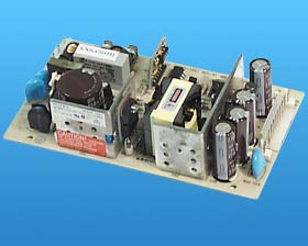
http://www.mpja.com/prodinfo.asp?number=12922+PS
MFG: AUTEC
P/N: UPS65-1051
Input: 115/230 VAC 50/60Hz
Output: 5V @ 13A
Specifications/Features:
Open switching supply. Over voltage/current protected, .5% line/1% load reg. Header pins In/Out.
L: 6" W: 3-1/2" H: 1-1/2" WT: .8
However, they do claim this, but I'm sure there would be more information to know for sure if it's being done right. It's hard to make a judgement based on just the marketing info.
The 17A on line two ought to be switched with the 7A on line one... otherwise it makes no sense.
Obviously the specs are dyslexic. You'd have to buy one and test it.

Similar threads
- Replies
- 29
- Views
- 908
- Replies
- 3
- Views
- 869
- Replies
- 2
- Views
- 1,165