Okay, yes I am a new guy. I have been lurking for a long time though and just signed up so that I could post this thread.
There have been several threads here which have discussed bottom bracket drive systems which use the bottom bracket as the jack-shaft to combine the power of the motor and the human pedal power. An excellent well known example is the Stoker Monkey set-up which uses a tandem crank on the left side that the motor is attached to by a second chain. And thus the bottom bracket itself serves as the jack-shaft although the motor spins the pedals as well and there is no obvious way to get around that if you are going to use the bottom bracket as the jack shaft with the motor chain and sprocket on the left side and the main drive chain back to the rear wheel is left "as is" on the right hand side.
After reading some of the past threads that discuss this arrangement I had a light-bulb go off in my head that others I think have hinted at but not put completely together. The idea comes from those counter-rotating propeller driven airplanes which have two propellers on the front one right behind the other that rotate opposite directions (to have zero or minimal torque load on the air frame due to the counter rotation). The important thing is that how they do that is by having a hollow drive shaft for the rear propeller with a smaller solid drive shaft going through the middle of it for the front propeller. Could not the same thing be done with the bottom bracket cartridge?
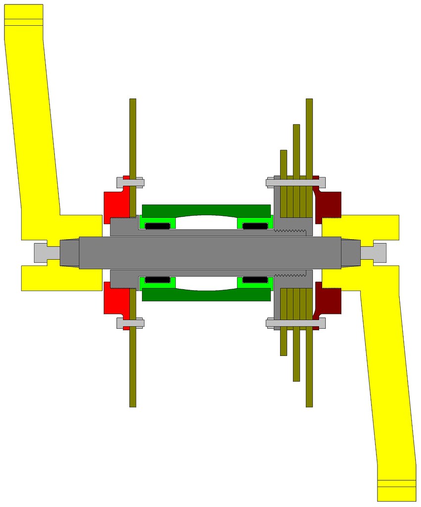
The pedals turning a solid shaft that is inside a hollow tube that forms a second shaft around the main shaft with the sprockets attached to the outer tube shaft and the inner shaft with the cranks and pedals attached to the outer shaft via. a freewheel crank assembly? Using approximate dimensions that are not completely to scale but close enough to be relevant I threw together the following diagram in my CAD program as a simple 2-D cut away and then printed it as a 16-color image that was just black lines on a white background and then used color fill in MS-Paint to color code the components:
Color Coding:
----- Dark Grey = Inner and Outer Drive Shafts
----- Solid Black = Needle Bearings
----- Light Grey = Bolts & Nuts
----- Bright Green = Threaded Cartridge Cup Ends
----- Dark Green = Bottom Bracket Tube of Bike
----- Gold-ish = Solid Chain Rings and Chain Ring Spacer Plates
----- Dark-Red/Brown = Standard Right Hand Freewheel Unit Threaded on Right Hand Threads to Right Crank Arm
----- Bright Red = Opposite Direction Left Hand Freewheel Unit Threaded on Left Hand Threads to Left Side of Outer Drive Shaft
----- Yellow = Crank Arms

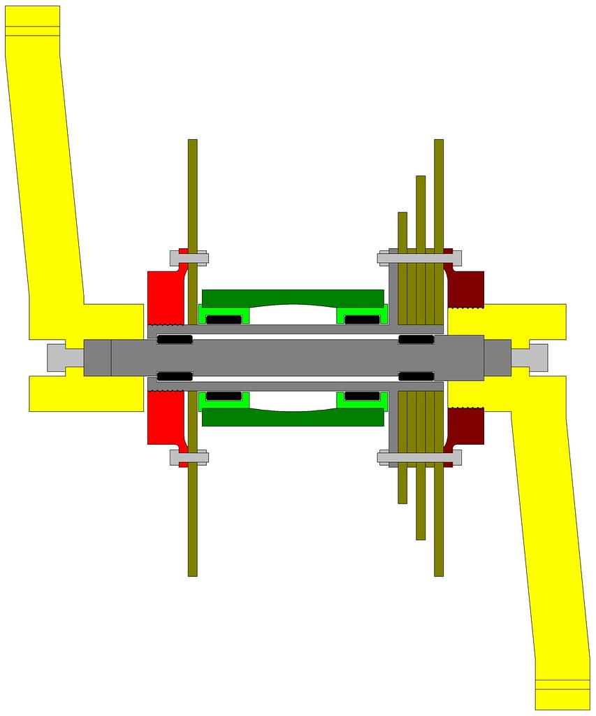
A custom bottom bracket set-up like that would allow the bottom bracket to serve as the jack-shaft (the outer hollow drive shaft) and transfer motor input from the left hand side chain ring to the front drive chain rings while allowing the inner drive shaft connected to the cranks and pedals to free-wheel while at the same time also allowing the inner drive shaft to drive the out drive shaft while the chain ring on the left side attached to the motor freewheels. Thus both crank pedals and the motor may independently drive the bike all through the front bottom bracket.
I think there is just barely enough room inside a standard 1-3/8” threaded bottom bracket cartridge to fit it all in provided needle bearings are used. As I drew it the outside diameter of the cartridge cups (Bright Green) are 1-3/8”. The needle bearings (Solid Black) are 1/8” diameter needles/rollers. The outer hollow drive shaft (Dark Grey) is a hollow tube that is always has at least 1/8” wall thickness. The inner drive shaft (Dark Grey) is mainly 1/2” diameter but thins down to just a little more then 3/8” diameter in the bearing races on either side, obviously minimal so it would have to be made of high end hardened steel (think drill rod stock). The right hand freewheel (Dark-Red/Brown) threads on the inside of the right hand side crank are standard dimension. The left hand freewheel (Bright Red) is a smaller non-standard diameter threads but it has to be that way in order to be able to assemble the unit.
I actually think it would be stronger then a standard free-wheel crank set-up since the chain rings at least on the right hand side are fully supported and bolted solidly to the outer drive shaft which passes completely through the bottom bracket with double bearing support.
So what do you guys think? We got a light bulb that is going to burn a while here or is it a flash in the pan dud of an idea?
There have been several threads here which have discussed bottom bracket drive systems which use the bottom bracket as the jack-shaft to combine the power of the motor and the human pedal power. An excellent well known example is the Stoker Monkey set-up which uses a tandem crank on the left side that the motor is attached to by a second chain. And thus the bottom bracket itself serves as the jack-shaft although the motor spins the pedals as well and there is no obvious way to get around that if you are going to use the bottom bracket as the jack shaft with the motor chain and sprocket on the left side and the main drive chain back to the rear wheel is left "as is" on the right hand side.
After reading some of the past threads that discuss this arrangement I had a light-bulb go off in my head that others I think have hinted at but not put completely together. The idea comes from those counter-rotating propeller driven airplanes which have two propellers on the front one right behind the other that rotate opposite directions (to have zero or minimal torque load on the air frame due to the counter rotation). The important thing is that how they do that is by having a hollow drive shaft for the rear propeller with a smaller solid drive shaft going through the middle of it for the front propeller. Could not the same thing be done with the bottom bracket cartridge?
The pedals turning a solid shaft that is inside a hollow tube that forms a second shaft around the main shaft with the sprockets attached to the outer tube shaft and the inner shaft with the cranks and pedals attached to the outer shaft via. a freewheel crank assembly? Using approximate dimensions that are not completely to scale but close enough to be relevant I threw together the following diagram in my CAD program as a simple 2-D cut away and then printed it as a 16-color image that was just black lines on a white background and then used color fill in MS-Paint to color code the components:
Color Coding:
----- Dark Grey = Inner and Outer Drive Shafts
----- Solid Black = Needle Bearings
----- Light Grey = Bolts & Nuts
----- Bright Green = Threaded Cartridge Cup Ends
----- Dark Green = Bottom Bracket Tube of Bike
----- Gold-ish = Solid Chain Rings and Chain Ring Spacer Plates
----- Dark-Red/Brown = Standard Right Hand Freewheel Unit Threaded on Right Hand Threads to Right Crank Arm
----- Bright Red = Opposite Direction Left Hand Freewheel Unit Threaded on Left Hand Threads to Left Side of Outer Drive Shaft
----- Yellow = Crank Arms
A custom bottom bracket set-up like that would allow the bottom bracket to serve as the jack-shaft (the outer hollow drive shaft) and transfer motor input from the left hand side chain ring to the front drive chain rings while allowing the inner drive shaft connected to the cranks and pedals to free-wheel while at the same time also allowing the inner drive shaft to drive the out drive shaft while the chain ring on the left side attached to the motor freewheels. Thus both crank pedals and the motor may independently drive the bike all through the front bottom bracket.
I think there is just barely enough room inside a standard 1-3/8” threaded bottom bracket cartridge to fit it all in provided needle bearings are used. As I drew it the outside diameter of the cartridge cups (Bright Green) are 1-3/8”. The needle bearings (Solid Black) are 1/8” diameter needles/rollers. The outer hollow drive shaft (Dark Grey) is a hollow tube that is always has at least 1/8” wall thickness. The inner drive shaft (Dark Grey) is mainly 1/2” diameter but thins down to just a little more then 3/8” diameter in the bearing races on either side, obviously minimal so it would have to be made of high end hardened steel (think drill rod stock). The right hand freewheel (Dark-Red/Brown) threads on the inside of the right hand side crank are standard dimension. The left hand freewheel (Bright Red) is a smaller non-standard diameter threads but it has to be that way in order to be able to assemble the unit.
I actually think it would be stronger then a standard free-wheel crank set-up since the chain rings at least on the right hand side are fully supported and bolted solidly to the outer drive shaft which passes completely through the bottom bracket with double bearing support.
So what do you guys think? We got a light bulb that is going to burn a while here or is it a flash in the pan dud of an idea?
")