mxlemming
100 kW
- Joined
- Jul 17, 2020
- Messages
- 1,209
I got a spare 5 hours to design a flyback and a few months later an evening and a half empty weekend to mess about with it.
Goal was not to make anything special, just to work out how flyback works, demystify it etc.
I used an NCP1377B control chip to allow up to 300kHz switching, a 250V MOSFET (also tried a 600V one but it makes no difference for my application) a self wound toroid and the cheapest opto isolator on JLCPCB. Topology was quasi resonant with a control winding and opto feedback.
Overall, I have concluded that buck converters are generally much more practical and efficient, but hey.
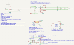
There's the schematic
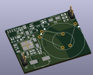
There's the layout/render, 30mmx40mm. I chose to use a toroid at first, which turned out to be a bad idea.
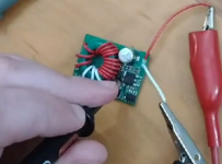
Actually building it with a wound transformer on a ferrite core I had.
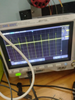
At light load it sits there pulse skipping
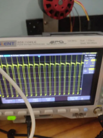
At high load, it is in QR mode (quasi resonant) and you can see the overshoot due to transformer referred flyback voltage.
Well, there we go. Built a flyback. It is interesting, but the power density compared to a buck converter is really low since 1) QR control means the inductor can only be used up to half current on average since it is driven with a triangle wave of current which includes the zero current state and 2) the duty cycle means it has discontinuous generation. Works happily with 90V in and 15W at 12V out.
Might be useful one day. I understand flyback converters now at least!
Goal was not to make anything special, just to work out how flyback works, demystify it etc.
I used an NCP1377B control chip to allow up to 300kHz switching, a 250V MOSFET (also tried a 600V one but it makes no difference for my application) a self wound toroid and the cheapest opto isolator on JLCPCB. Topology was quasi resonant with a control winding and opto feedback.
Overall, I have concluded that buck converters are generally much more practical and efficient, but hey.

There's the schematic

There's the layout/render, 30mmx40mm. I chose to use a toroid at first, which turned out to be a bad idea.

Actually building it with a wound transformer on a ferrite core I had.

At light load it sits there pulse skipping

At high load, it is in QR mode (quasi resonant) and you can see the overshoot due to transformer referred flyback voltage.
Well, there we go. Built a flyback. It is interesting, but the power density compared to a buck converter is really low since 1) QR control means the inductor can only be used up to half current on average since it is driven with a triangle wave of current which includes the zero current state and 2) the duty cycle means it has discontinuous generation. Works happily with 90V in and 15W at 12V out.
Might be useful one day. I understand flyback converters now at least!
Last edited:

