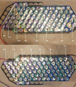
You wrote 13S6P. but you built a 14S-6p. Typo, right?
It's tough to weld and keep alignment. Some of your strips and welds are off center. Next time, use the thick paper washers on the positive ends. Some of your welds missed the positive cap and are close to the edge of the cell where the negative case wraps around. You don't want to melt thru the cell's PVC washer and leave a possible place to short out in the future.
Like the previous post said, there's not enough series connects, the ones that go from positive end of one cell to nearest negative end of the next. Suggested routes were marked in blue. Next time, put those down first, using metal that can handle the series current. Then you can put down a lighter piece of metal for the parallel. When you stack strips, the second layer is harder to weld well so it's better if it doesn't have to carry much current. Better yet, buy the stamped nickel patterns for the holder. Often, they're just nickel plated steel, but that still works better than most DIY patterns. What thickeness. .10mm, .15mm or .20 mm , were your strips anyway?
If all those colors implies different brands and types of cells, you might get mixed performance. EDIT: I see from your prior post that they
re all the same, but are salvaged cells. Good luck.
Here's what the BMS connects look like to me. Walk a voltmeter from the black wire on each side all the way to the red to verify that the voltage goes up by a cell on each step. Do it again on the balance connector after you wire it, before you plug it in. Too easy to cross a pair of wires. We've all done it. If you weld a short niclel tab to each B connect, it's a ;ot easier to solder.
If this goes into a Hailomg case. buy that Kapton tape and cover all the metal.


 View attachment Battery Layout 13S6P.pdf

 View attachment Battery Layout 13S6P.pdf


