dirty D's e-bike #2

$20 that sounds good, the guy at the "bike shop" told me id have to go to a machine shop to have it done and it would cost a fortune. you would think that the guy that owns that "bike shop" would have heard of headtube and seattube reaming before.
 
well more metal for the seat tube and the head tube got delivered today, not much work to put it together just has to cut the main tube to the right length and fish mouth the end of it to accept the head tube. for the seat tube i drilled out two 1 1/4" holes with a hole-saw making sure to drill at 75 degrees. the seat tube fit in very nicely and i temporarily tack welded it in place, i want to actually sit on this bike before i make the seat tube permanent.

the current weight of the frame is 12 pounds.
 

Attachments

  • weld.jpg
    weld.jpg
    24.5 KB · Views: 3,135
  • ta-da.jpg
    ta-da.jpg
    44.1 KB · Views: 3,135
  • perfect-fit.jpg
    perfect-fit.jpg
    28 KB · Views: 3,135
  • head-welded.jpg
    head-welded.jpg
    43.4 KB · Views: 3,132
  • temporary.jpg
    temporary.jpg
    45 KB · Views: 3,132

Nice work Dirty. Those welds look great. You may have inspired me to get a cheap tig welder.

I bought my seatpost as "bicycle tubing" instead of from the metal yard. It was expensive, but it was made to fit a seatpost.

You should be able to find a really cheap hub. I bought one for $6.

Keep up the good work. The bike looks great (and only 12lbs).
 
ta_da_182.jpg


The seat tube angle normally parallels the head tube angle. (within a few degrees) You need to significantly tilt that backwards or your seat will be too far forward. (it looks strange)

:arrow: Also, what wheelbase and steering head angle are you using?

I've calculated that a 52" wheelbase and 70 degree head angle ends up producing a truly "square" relationship of the frame to the head tube. In other words if your wheelbase is 52" your head tube relationship to the frame should be 90 degrees. So I suspect you aren't using a 52" wheelbase. (or you will get a very steep head angle)
 
the wheelbase will be 52" and the head tube angle will be about 68 degrees, the angle and wheelbase depends on the length of the fork too, but it will be about 52" and 68 degrees. it looks strange in the picture because the frame isn't at the same angle as it would be with wheels on it. the distance from the middle of the seat to the handlebars will be about 26.5".
 
Hi Dirty:

I tried to build a sprocket myself. Yours looks really good. I'm sure it will work. However, to get it to run smoothly, I think you need to make the teeth more pointy. If you removed those square edges it would allow the chain to more gradually seat onto the sprocket. The way you have it now, the chain has to seat correctly immediatly when it hits the sprocket. If you can curve those edges, it will "roll" into its slot. Keep in mind that as it spins, all the other chain links are seated, so the ones entering the sprocket don't have to be seated immediately. They aren't required for friction.

<img src="http://endless-sphere.com/forums/files/sprocket3_945.jpg">

Look at this picture of a white industries sprocket. Imagine how the chain may not even touch the sprocket until its on it.
 

Attachments

  • DSCN0611.JPG
    DSCN0611.JPG
    54.7 KB · Views: 3,055
i dropped my frame off at a bike shop and they are going to ream the headtube and seattube out and press in the headest cups, i got the fork from UPS today, there is a crack in the outer leg/arch casting it will probably be just fine for on road use but it still bugs me, maybe i will order a replacement part it cant be that much. tomorrow i will pick up the frame and get the stem and handlebars from UPS. maybe ill be able to put some wheels on it and a seat and roll around with it 8) . pretty much the only major thing i need to get next is a rear wheel with a disc brake hub, i was going to use my shitty $50 bike rear wheel and fabricate and weld on a disc brake mount but its not a 135mm wide wheel its a lot shorter, the guy at the other bike shop said it would be about $60 to lace a wheel if i got the parts, screw that. after that i just have to weld together a battery box out of the smallest angle iron i can find, id love to use aluminum but my tig welder is DC only, i think it would be possible to built some kind of inverter to switch the output of the welder to square wave AC with some MOSFETS and crap, maybe have a knob to adjust the +/- balance to tune the cleaning action of electrode positive and penetration of electrode negative. fechter im waiting for your opinion on this :D
 
Maybe you can use a modified Crystalyte controller :D

How many amps is the TIG?

If aluminum is out, I'd go for stainless steel.
 
its 180 amps max, for this whole project I've been using about 40-80A, stainless is even heavier than mild steel or chrome-moly.
 
i went to pick up my frame today and the guy said he couldn't ream the headtube or seattube out because its not close enough to 27.2mm ID in the seattube and 33.8mm ID in the headtube, i guess those types of reamers only remove a couple thousandths of metal at most, i needed like 20 thousandths removed. i used a dremel to make the headset cups fit in the headtube, its not perfect but its good enough. i used the dremel to get the first 3" of the seatpost to fit into the seattube and that took hours, i dont know how im going to get it to fit all the way. i put some wheels on it to see what it looks like.
 
That looks great. I bought mine here. The woman who answered the phone asked my seatpost size and sold me a tube that would fit. I bet steel is cheaper.

http://www.fairing.com/bicycle_frame_depot.asp?subcat=home

Also, since she asked the size, that must mean that there are different sizes of seatposts. Perhaps you can find a bigger seatpost so you don't have to reem it, or reem it less.


This is looking great. Can't wait to see the finished article.
Would a 26.8 mm seat post be too small? You've probably already considered it, but couldn't you turn down the seat post intead – it's only a few tenths of a millimetre.
 
a 26.8mm seatpost would fit perfectly as the ID of the seattube is 26.9mm, the only thing is i cant find a suspended seatpost that is 26.8mm at a decent price, but i do have a 27.2mm suspended seatpost on another one of my bikes that i was going to use.
 
well im glad i only tack welded the seattube in, i used my dremel to cut the welds and take the seattube out, i used the rest of the 1.5X.095" wall tubing as the new seattube(i bought 24" i only needed 11.5"). there is no way i could have reamed that tube out to 27.2mm without the right tools, ive decided to just go with a 26.8mm seattube or a 25.4mm seattube with a 26.8mm shim. the ID of the seattube is 1.060"(26.92mm) i guess a 26.8m seatpost is exactly 26.8mm so the tube is about .004" bigger than the seatpost, i think thats about right the fit should be close enough to not have any noticeable play but it should still slide in and out easily. i never really noticed that a lot of bike part dimension that are in metric are actually based on really round numbers in the imperial system, my tubing is 1.25" OD which is 31.75mm, 31.8mm seattube clamps are a common size, i guess they are made to fit American made tubing in inches. my wifes bike has a 31.8mm seattube clamp, it fits my tubing perfectly ill be using this until i get my own :lol:. i drilled a .25" hole 4" down from the top of the seattube and then used my grinder to cut a slit to it, i guess a hole at the end of the slit distributes the stress more evenly than just the slit ending there when you clamp it.
 
The rounded hole at the end moderates the stress concentrator that would result at the end of a straight cut. A high stress concentrator from the straight cut would initiate a fatigue crack that could spread down the tube. Cracks are great stress concentrators themselves, so have a tendency to propogate.
 
im going to use my $50 wal-mart bike rear wheel as my temporary rear wheel on this bike, im going to make a disc brake caliper mount onto the hub. i went to the hardware store to get some M6 .80 pitch nuts and bolts(thats what size the bolts are that hold disc calipers on), they dont have any, im not positive but i dont think M6 .80 pitch is a standard size, all they had in M6 was 1.00 pitch. im just going to use 1/4" 28tpi standard bolts and nuts for this wheel. the disc hub to sprocket adaptor will use 1/4" holes anyhow, very close to 6mm so that when i get a real rear wheel with a disc brake hub i can just get the correct M6 .80pitch bolts and attach the adaptor. i got 6 feet if 1/8"X1/2" angle iron and 6 feet of 1/8"X1/2" flat bar to make the battery box today.
 
See the other threadd, I think it's M5 x 0.8 (a standard size), not M6.
 
today i built the battery box and welded the mounts it will bolt to onto the frame. it will hold four 12V 12AH batteries. i also welded on a 6 bolt mount onto my wal-mart bike wheel for the sprocket adapter im going to make next, the only problem is that i thought the international standard 6 bolt disc mount used M6 bolts but it uses M5 bolts, i drilled 1/4"(6.35mm) holes in the plate that i used as the mount and welded 1/4"X28tpi nuts to the other side, i was going to make the adapter have 1/4" holes so that it would fit this ghetto hacked up wheel mount with 1/4" bolts and also fit a real disc brake hub that i thought had M6 threaded holes, the hubs really have M5 threaded holes so if i use 1/4" holes in the adapter there is going to be excessive play and the adapter wont be centered on the hub. i guess im just going to have to make a new adapter when i get a new rear wheel CRAP!

EDIT: actually ill just make two sets of holes in the adapter 1/4"(6.35mm) holes for M6 bolts or 1/4" bolts, and 13/64"(5.16mm) holes for M5 bolts.
 

Attachments

  • battbox.jpg
    battbox.jpg
    34.7 KB · Views: 3,169
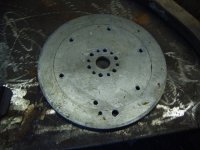
today i made the sprocket adapter and put the sprocket on my old wheel, i threw it all together with electrical tape holding all the electronics in place :shock:, just temporarily though i just had to try it today. i forgot to add the support arm for the motor mount so as soon as i hit the throttle the motor mount bent, i bent it back and welded a temporary support in. i lost my motor shaft nut that holds the motor sprocket on, i dont know when it fell off but the sprocket stayed on the whole time the nut was off. does anyone know where to get that kind of nut? im not sure what size it is but it is reverse threaded. i threw the speedometer on after it was dark and i couldn't really read it i think it said either 31 or 41 mph, it felt a lot faster than 31 so i hope it was really 41 :lol: , i calculated the top speed as 35 mph but maybe since the posture is more like a racing bike and my feet were on the motor(yes really) there was less air resistance than i calculated. the seatpost off my fathers old racing bike sort of fit in my seattube its something less than 26.8mm and more than 25.4mm.
 

Attachments

  • adapter1.jpg
    adapter1.jpg
    32.7 KB · Views: 3,123
  • adapter2.jpg
    adapter2.jpg
    52.8 KB · Views: 3,124
  • adapter3.jpg
    adapter3.jpg
    44.9 KB · Views: 3,123
  • assembled.jpg
    assembled.jpg
    76.5 KB · Views: 3,121
  • quickfix.jpg
    quickfix.jpg
    65.3 KB · Views: 3,120
  • wheel.jpg
    wheel.jpg
    61.8 KB · Views: 3,119
So,

You couldn't wait, didn't know how fast you were going, lost your nut in the dark and things got bent after that...

(TMI - I didn't really need to know about yer dad's tube either.)

:shock:
 
Nice work Dirty. I swear my bolts were 6mm. I took an example bolt from a set, and it was clearly marked 6mm. I don't know what went wrong. Sorry if it made extra work for you.
 
thats alright, were talking about the same bolts right? the ones that hold a 6 bolt disc rotor on? if there are 5 or 4 bolts its a different standard. it may be M6 but are you sure about .80 pitch, if i do a google search for M6 .80 pitch i get nothing, it seems M6 bolts are made in no other thread pitch than 1.00mm.
 
I think you're right. I went to take a picture to show you, and you're right--its says m6-1.0. I know I saw the "0.8 ", so I must have misread the "5" as a "6." I have to read it through a plastic lid, so its definately possible. Sorry. They must be m5-0.8.

I realized that our bikes are much the same. We should do a comparison of performance at different current levels to measure efficiency. I'd like to know if I'm losing power in my gear hub. For example, if we both run 15 amps on flat land, and my bike goes 20mph, and your goes 25mph, it would tell us how much power I'm losing using the Nuvinci gear hub. Also, I'd like to know how much I'm gaining on hills. You may be losing a bit of power due to slower RPMs. It would help us understand better how to design in the future. Do you have an ampmeter?

Our bikes should be roughly the same weight, and I could disconnect a battery or two to make them the same voltage.
 
dirty_d said:
thats alright, were talking about the same bolts right? the ones that hold a 6 bolt disc rotor on? if there are 5 or 4 bolts its a different standard. it may be M6 but are you sure about .80 pitch, if i do a google search for M6 .80 pitch i get nothing, it seems M6 bolts are made in no other thread pitch than 1.00mm.
Beagle123 said:
I think you're right. I went to take a picture to show you, and you're right--its says m6-1.0. I know I saw the "0.8 ", so I must have misread the "5" as a "6." I have to read it through a plastic lid, so its definately possible. Sorry. They must be m5-0.8.

M6 x 0.75mm pitch is in the ISO Metric Fine Pitch Series.

Yes, 0.8mm is standard pitch for M5
 
M5 .80 pitch, good i drilled a set of 5mm holes im my sprocket adapter in case they were M5 instead of M6, all is well :) .

beagle, do you have the 48V model of the MY1020 1200W motor, or the 36V? it would be good to do a performance comparison, if yours is 36V then the comparison wil get a little more complicated.
 
Back
Top