Hi,
The lead batteries of my e-scooter vastro (2kw DC hub motor) died a few years ago alongside the controller. The escooter took then some dust in my garage. But it hurt my feelings to either sell it ot worse let it rust. So I decided to upgrade it.
First thing, I replaced the faulty controller with a votol EM50-4. I purchased a so called 40Ah 72V at ali.expresss and at first, scooter worked. But I soon discovered that 40Ah was in reality only 15Ah... And I've realized sadly afterwards hat a lot of chinese battery sellers are liars. After 3 unsuccessful purchase attempts (hopefully refunded), I decided to build my own 45Ah battery. My main constraint: volume. So I had to design a 20S9P battery on two layers.
I ordered 180 samsung 50E 21700 cells at nkon (nl). Fast shipping.
And I ordered all the others stuff to build the battery:
- welding machine
- nickel busbar
- epoxy plates
- insulated paper
- gasket
- polyamid tape
- holder bracket
- thermo-retractable PVC
- fiberglass tape
- bms JK-BD6A20S10P
Here are the steps (sorry, no video, only pictures):
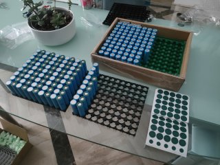
1/ fill in gasketed cells in holder brackets:
2/ welded cell with busbars with insulating polyamid and paper:
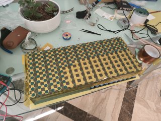
3/ bend the flat pack to 2 layers separated by a 2mm epoxy plate and prepare the rows for the bms wiring:
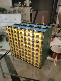
4/ wrap up with insulated paper and stick the bms:
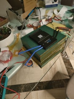
5/ connect the bms wires to each rows (schema are quite clear) and sorry, I've lost the photo with the wirings...
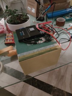
6/ Full enclosure with 1mm epoxy plates and with XT60 charge and XT90 discharge connectors
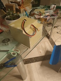
7/ double protection with PVC and straps (15kg !), custom steel sheet to protect the battery in the enclosure
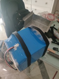
8/ Finally, the battery is in the escooter enclosure:
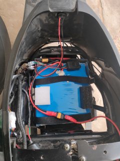
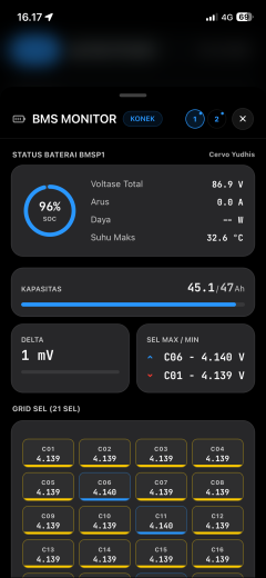
Since the JK BMS embeds BT and the initial analog soc gauge was only fit to manage lead battery, I used a lilygo chip (ESP32) to connect through BLE to the BMS and display real time SOC, voltage and current discharge/charge:
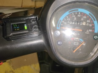
To be honest, Claude.ai wrote almost entirely the initial program (C++, ARDUINO IDE) following my specifications:
- display SOC (number and gauge), voltage and current
- button up: long press activates wifi for OTA
- button down:
- short press : switch SOC/remaining distance
- long press: force last choice (SOC/remaining distance) at start up.
The lilygo has an initial enclosure. I designed a larger PETG enclosure (freecad/anycubic kobra 2plus) and use some silicone tape to make it waterproof.
Quick comparison before/After:
Approximative cost: 800 €
As you can see, the gap is clear in term of performance so it was worth the effort. I hope it will motivate some of you, just for the fun !
The lead batteries of my e-scooter vastro (2kw DC hub motor) died a few years ago alongside the controller. The escooter took then some dust in my garage. But it hurt my feelings to either sell it ot worse let it rust. So I decided to upgrade it.
First thing, I replaced the faulty controller with a votol EM50-4. I purchased a so called 40Ah 72V at ali.expresss and at first, scooter worked. But I soon discovered that 40Ah was in reality only 15Ah... And I've realized sadly afterwards hat a lot of chinese battery sellers are liars. After 3 unsuccessful purchase attempts (hopefully refunded), I decided to build my own 45Ah battery. My main constraint: volume. So I had to design a 20S9P battery on two layers.
I ordered 180 samsung 50E 21700 cells at nkon (nl). Fast shipping.
And I ordered all the others stuff to build the battery:
- welding machine
- nickel busbar
- epoxy plates
- insulated paper
- gasket
- polyamid tape
- holder bracket
- thermo-retractable PVC
- fiberglass tape
- bms JK-BD6A20S10P
Here are the steps (sorry, no video, only pictures):
1/ fill in gasketed cells in holder brackets:
2/ welded cell with busbars with insulating polyamid and paper:
3/ bend the flat pack to 2 layers separated by a 2mm epoxy plate and prepare the rows for the bms wiring:
4/ wrap up with insulated paper and stick the bms:
5/ connect the bms wires to each rows (schema are quite clear) and sorry, I've lost the photo with the wirings...
6/ Full enclosure with 1mm epoxy plates and with XT60 charge and XT90 discharge connectors
7/ double protection with PVC and straps (15kg !), custom steel sheet to protect the battery in the enclosure
8/ Finally, the battery is in the escooter enclosure:
Since the JK BMS embeds BT and the initial analog soc gauge was only fit to manage lead battery, I used a lilygo chip (ESP32) to connect through BLE to the BMS and display real time SOC, voltage and current discharge/charge:
To be honest, Claude.ai wrote almost entirely the initial program (C++, ARDUINO IDE) following my specifications:
- display SOC (number and gauge), voltage and current
- button up: long press activates wifi for OTA
- button down:
- short press : switch SOC/remaining distance
- long press: force last choice (SOC/remaining distance) at start up.
The lilygo has an initial enclosure. I designed a larger PETG enclosure (freecad/anycubic kobra 2plus) and use some silicone tape to make it waterproof.
Quick comparison before/After:
| lead battery (6x12V packs) | Li-ion battery 45Ah 72V | |
| weight (kg) | 22 | 15 |
| speed (km/h) | 45 | 55 |
| autonomy (km) | 25 | 95 |
Approximative cost: 800 €
As you can see, the gap is clear in term of performance so it was worth the effort. I hope it will motivate some of you, just for the fun !
Last edited: