DIY Li-ion battery: first connect cells in series, then in parallel

kilou

10 W
Joined
Aug 25, 2014
Messages
87
Hi,

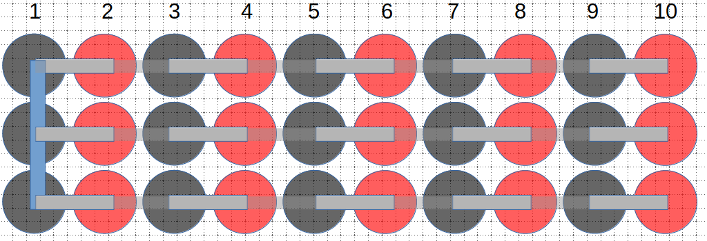
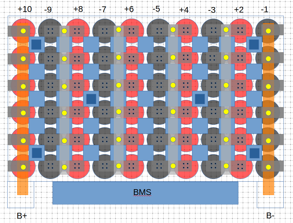
when building a Li-ion battery, it seems usual to first build groups of parallel cells and then connect these in series. Is it actually safe to do it conversely: first build groups of cells in series and then connect these groups in parallel?

I understand that groups of cells connected in series should have the same capacity when using the battery. If that is not the case, cells with lower capacity will get depleted before others etc which is not good. But this all apply when you're loading the battery. During the build, when first building the series connections and then the parallel ones, you'll be effectively connecting cells in series that do have different capacity (e.g. when placing the first parallel connection, the first group of cells will have a larger capacity than cells that are not already connected in parallel). But during the build process, no load is applied to the battery so this shouldn't matter right? Of course, when all parallel connections are placed, all cells have the same capacity and there is no longer any problem of course.

Is that correct or am I missing something? I'd be interested in first building the series connections and then the parallel ones in my build because it would be easier with my layout. But I just want to make sure this would not result in any adverse event...

Thanks
 
kilou said:
seems usual to first build groups of parallel cells and then connect these in series. Is it actually safe to do it conversely: first build groups of cells in series and then connect these groups in parallel?
Actually most spot-welded packs do them both at the same time, just a question of which are more directly attached to the cells.

For very high C-rates some smart members say Serial First is better, since that is the higher current flow.

But yes, either way is equally safe.

I do not grok at all what you are saying about different capacities while building - I think you are imagining something there that is not the case. All cells should be at exactly the same SoC/voltage, capacity/SoH etc before you start.

IMO do not bother with scrap cells.
 
If you are doing Series-first

consider making those strings "sub-pack modules"

and rig a way to parallel them easily in various capacities

to give flexibility for different range / speed rides.


Unless your EV is a car, as opposed to say a bike.
 
It seems obvious that it is easier to assemble a pack in paralleled groups first. However, if you are using a roll of nickel ribbon, and then stacking them on top of each other to achieve both series and parallel connections, that might add another layer of nickel for the current to pass through.

If you pay extra to get high-amp cells, and then you hope to draw high amps from the pack, the construction details can have a measurable effect on voltage drop due to resistance in the complete length of the current path.

A common pack build might use a style of nickel bus that is shaped like a ladder, and it accomplishes the series and parallel connections at the same time with a single layer of nickel sheet.

For a high current pack, I would recommend using the copper sandwich method to connect the series connections first, for the shortest current path, lowest resistance, and the coolest material. Using pure nickel for series current converts a lot of battery watts into waste-heat. Copper buses also pull heat out of the cell as a heat-sink.

The parallel connections can be thin and narrow nickel ribbon on top of the series connections, because they carry very little current under all conditions.
 
john61ct said:
I do not grok at all what you are saying about different capacities while building - I think you are imagining something there that is not the case. All cells should be at exactly the same SoC/voltage, capacity/SoH etc before you start.

IMO do not bother with scrap cells.

My wording was probably inadequate, sorry. What I meant was that if you build say 6 separate strings of 10S1P with exactly the same 18650 cells and then add the a strip to connect the first cell in each of the strings in parallel, the first "cell" (i.e. parallel group) is now composed of 6 18650 cells connected in parallel (thus its capacity is 6 times the capacity of a single cell) while the other cells which are not yet connected in parallel would still have the capacity of a single cell. Don't know whether that is properly expressed though.

Anyway, you answered my question and I feel safe about going with series connections first. Thanks!
 
List to SM not me if any difference, he da man.

kilou said:
if you build say 6 separate strings of 10S1P with exactly the same 18650 cells and then add the a strip to connect the first cell in each of the strings in parallel, the first "cell" (i.e. parallel group) is now composed of 6 18650 cells connected in parallel (thus its capacity is 6 times the capacity of a single cell) while the other cells which are not yet connected in parallel would still have the capacity of a single cell

No, once the group is wired in parallel, functionally that is a single big cell.

Groups being connected in series, are no longer being connected at any single-cell level, only the group as a whole can be connected in series to the next group.
 
Some existing discussions about this:

https://endless-sphere.com/forums/search.php?keywords=series*+parallel*&terms=all&author=&sc=1&sf=titleonly&sr=topics&sk=t&sd=d&st=0&ch=300&t=0&submit=Search

Not all the results above are relevant, but you can tell by title which ones to start with.

There are others not found by that search.
 
If you just connect multiple cells in “series strings” of 10 , and connect those 6 strings in parallel, then you will need a BMS for every individual cell ! iE,..60 BMS’s :shock: 👎
Whilst cells connected in “parallel groups” of 6 first, then connect those “groups” in series to 10s, you only need 1 BMS for each “parallel group”......so 10 BMS’s :bigthumb:
.. unless of course you plan to “go commando” with no BMS ? :eek:

However , what you have suggested is exactly what some of us do with RC Lipo “bricks” which are normally 5S or 6S as they are built, and we then connect them in series for 10S,...the parallel sets of those for more capacity as required.
So yes, it is done commonly, but the BMS is commonly ignored at the owners risk !
 
I was thinking about a situation like this, considering for example a 10S3P battery.

7CuwxDQ.png


Suppose that I have 30 cells each with a capacity of 1C and I start by making the 3 series strings (grey connections) and then start with the first parallel connection (blue). At this time of the build, I was thinking the first "cell" in the battery is now composed of 3 18650 cells connected in parallel, so its capacity is 3C while the other not yet connected in parallel would still be 1C. However I must be wrong because a single parallel connection as in the above diagram effectively parallels all the cells at once I guess. So at this precise time point, the battery already have 10 "cells" (i.e. parallel groups) with each one having a 3C capacity. So I guess my worries were pointless. I'm not sure to get the point about the BMS though. A BMS is always added at the end of the build, when all series and parallel connections are made. So it shouldn't matter how the build is performed (parallel first or series first), at the end the battery is the same and a single BMS monitoring all 10 cells will be needed. Or am I seeing it wrong?

EDIT: diagram corrected
 
:shock: What you have shown is impossible to assemble with any voltage in the cells, and would burst into flames if you tried to charge it !
If you Do not understand the problem here, ..or the point about the BMS requirements, then i urge you not to attempt to assemble a battery until you have researched and read more on the subject.
 
spinningmagnets said:
A common pack build might use a style of nickel bus that is shaped like a ladder, and it accomplishes the series and parallel connections at the same time with a single layer of nickel sheet.

I'm thinking about building a DIY 10S6P battery pack using new Samsung 29E cells bought with Z-solder tabs already spotwelded on them (as I don't own a spotwelder myself). In another thread, Hillhater pretty much convinced me to avoid bolts/nuts connections so I'm now considering soldering the tabs together to form series connections first, and then add parallel connections later on. The solder tabs are 8mm wide and 0.15mm think (30mm long but I will shorten these). The idea is to drill a hole in the solder tabs where the cells would be connected together, stick a copper nail (orange) in that hole and then solder each tab to that copper nail. Finally the parallel connection would be added on top (grey), as on the following figure:

awpZeaX.png


The copper nail may not be needed but I was thinking it would add some strength to the soldered connection, slightly lower resistance too but most importantly would make it easier to solder the tabs together without transferring too much heat to the cells. The whole pack would look like this, with parallel connection (light grey) made using Nickel strips (maybe 6mm wide, 0.15mm thick):

7nAnlmJ.png


Yellow dots show the locations of the soldered connections with the Copper nails etc. The battery positive and negative terminals would use either a copper strip with tabs folded over it and soldered to it again using a copper nail or I may also directly solder a thick cable to each battery tabs. I didn't figure that out yet. A BMS would be added at the end.

I intend to draw max 20A from this pack so that's about 3.4A per cell. I guess that series connections made out of two nickel tabs one on top of the other over probably half of the connection's length should be enough to handle that but I'd like to be safe and have some room. Do you think that build would be adequate? Do you see a problem with such layout?

Alternatively I could also use copper strips (instead of nickel) to build the parallel connections. I understand that copper would be most useful for series connections and not parallel ones but I'm kind of constrained by using nickel for the series since these would be formed by the tabs. However if I sandwich a copper strip for parallel connection in-between the two tabs, the series connection would look like this:

wEy8zUo.png


So the series connection would also benefit from a little bit of added copper, which should help lower the resistance too. Is that worth it for you?
 
Hillhater said:
:shock: What you have shown is impossible to assemble with any voltage in the cells, and would burst into flames if you tried to charge it !
If you Do not understand the problem here, ..or the point about the BMS requirements, then i urge you not to attempt to assemble a battery until you have researched and read more on the subject.

I would NOT charge or discharge such a battery at that time. It is all about a step in the building process... I agree I messed up the series connection in the diagram, was just trying to do it quickly but it is obviously wrong. Please look at my previous post to see a diagram for the complete build...which shouldn't burst into flames hopefully.

EDIT: diagram is now corrected in post https://endless-sphere.com/forums/viewtopic.php?f=14&t=106455&p=1559593#p1559593
 
I think I'll end up using M2 bolts and nylok nut instead of solder to secure the tabs between cells. The connections would look like this (I may still add a washer below the nylok nut):

DhFBqbm.png


Keeping everything Nickel plated should avoid any corrosion issue. The series connection would thus be composed of two nickel tabs 8mm wide and 0.15mm thick each bolted together. I intend to draw max 20A from this 10S6P pack which should be about 3.4A per cell. Since a single 7x0.15mm nickel strip is supposed to handle 5A, I guess I should be good with this setup although the double strip would only run over approx 1/3 of the series connection and there should be some contact resistance. The M2 bolt's head would probably be soldered onto the parallel strip so that the nylok can be secured by holding the strip straight (otherwise the head may twist while screwing the nylok nut I guess).
 
The main thing here, is that if you series first, you will have 6 batteries. No way one bms can handle it.

From what I have seen, series first has been used mostly with hobby king packs, and no bms. they come in series first, so you are typically doing a series first type arrangement. Sometimes, series, then parallel, then series some more. Its mostly just done series first for wiring convenience more than anything else.

Your pack ought to be P first. But you can do two 3p packs, and two bms's if you like.
 
Thanks for your reply dogman dan. I think there may be some misunderstanding about what I intend to do. I understand that building series first effectively means building 6 10S1P batteries. But if all the individual cells (from all these 6 batteries) have exactly the same voltage, I don't get why it wouldn't be possible to parallel these 6 batteries at the cell level and build a single 10S6P pack, as shown on the diagram a few posts above. This pack can then be monitored with a single BMS made for a 10S i.e. 36V pack. Why would I need 6 BMS? I'm not saying that I want to parallel these 6 batteries globally (in which case indeed I'd need 6 BMS). What I would like to do is first make the 6 series groups, and then join each cell of one battery together with the corresponding cell of the other batteries using nickel strips (see vertical light grey bands the diagram below)

7nAnlmJ.png


So the parallel connections would be made at the cell level, not at the battery level! Doing series first in my case is just for convenience during the build process but my goal is to end up with a single 10S6P battery with groups of parallel cells connected together using nickel strips. The end product should thus be exactly similar to a pack that is built parallel first then series.
 
Hillhater said:
.. unless of course you plan to “go commando” with no BMS ? :eek:

In fact this is what I plan to do: no BMS but charging using a hobby balance charger (incl. temperature sensor) + use 2 lipo checkers as low voltage alarms, as suggested by Shawn McCarty in this video.

https://www.youtube.com/watch?v=pljSZcEwc8Q

Still trying to find out whether the fact that such lipo alarms only drain power from the first cell will have real life effect on cell balance though...
 
If you want separately welded serial'd 1P sub-pack modules

then joined in parallel at the top and bottom pair for power

you can still join all the #1 cells together all the #2 cells together, etc in parallel directly

so your single **easily removable** BMS and/or voltage checker and/or balancer

can manage the whole pack at the group-level rather than per-each-cell requiring a BMS for each string separately.

This will be true for 3P, 6P, 8P whatever, the only change is the Ah capacity per group.

Choose to ride with a volt checker or BMS, sometimes go without.

Take everything off so the batteries are stored isolated when not in use.

Decide your sub-1A balancer is too slow or not adjustable enough, buy a 2A or 5A one, or use an RC charger instead.

Depending on how you wire your intraconnects you will be able to sometimes ride light, other days need long range beef up the pack.


kilou said:
So the parallel connections would be made at the cell level, not at the battery level! Doing series first in my case is just for convenience during the build process but my goal is to end up with a single 10S6P battery with groups of parallel cells connected together using nickel strips. The end product should thus be exactly similar to a pack that is built parallel first then series.

If your pack will end up all pretty much permanently spotwelded together, there really is not much difference, S&P connections can also happen at the same time with a laser-cut plate rather than using strips.

If using strips. then just a question of which are directly attached to the cells - SM says serial needs the lower resistance more, so go with that.

 
kilou said:
Still trying to find out whether the fact that such lipo alarms only drain power from the first cell will have real life effect on cell balance though...

Just try and see yourself.

If after riding the balance is off, takes more than 5min to correct, either get a new checker (they're cheap)

or get a faster balancer.

The ability to make such judgment calls yourself, given your pack and your usage IRL

is actually much more valuable than the price of what gadgets you use.

What works for someone else "just fine" may not work well **for you**.


john61ct said:
If after riding the balance is off, takes more than 5min to correct, either get a new checker (they're cheap)
or get a faster balancer.
Good point! I think that's what I'll do. Anyway the balancing power is probably not going to be an issue (my RC charger can do up to 500mA to balance cells). That's probably more than what any reasonably priced BMS can do. Furthermore, by unplugging the cell loggers when not in use, the battery won't see any drain.
 
john61ct said:
If your pack will end up all pretty much permanently spotwelded together, there really is not much difference, S&P connections can also happen at the same time with a laser-cut plate rather than using strips.

That's what I wanted to read :) Indeed the pack will always remain in the 10S6P format with parallel connections being made at the cell level. So series first or parallel first doesn't matter.
 
not saying no difference, according to SM for very high C-rates, serial first lowers overall resistance.

Since this and related questions have come up in multiple threads recently,

I created a central one for that one specific issue

https://endless-sphere.com/forums/viewtopic.php?p=1561188#p1561188

To discuss your specific design, respond here only

leave that one for the "general science" question using that specific 1P6S example **please**.

If this question is no longer relevant for you, then just ignore it

 
I believe it's electrically safe to take six strings of 10S-1P and then make them into a 10S-6p, as long as all the cells have equal voltages. Probably want to start at the negative end and add the straps in sequence. I've put two 10S-2P strings in parallel like this to make a 10S-4P.

Whether it's mechanically safe is up to the user. I don't know about using screws. You'll probably drop one during the process and have a short circuit, plus it makes the package bigger than it needs to be.
 
Back
Top