DIY Shunt

brainfarth

100 mW
Joined
Feb 16, 2013
Messages
45
Location
Oregon City, Oregon
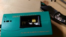
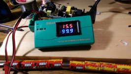
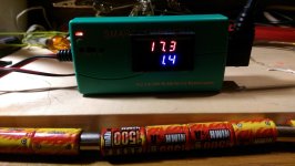
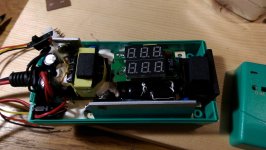
I had a Powerizer smart charger http://goo.gl/QZPavz that I wanted a voltage and amperage readout on. So I installed a cheap combo meter http://goo.gl/gVTYq7 on it. Somewhere down the road, I lost the original shunt for it. Not that I could ram something that large inside the case. So I'm wondering what steps would you take to make your own shunt that would be small enough to fit inside. The max output is 18 volts at 1.75 amps.
Charger (1) (Medium).jpg
Charger (2) (Medium).jpg
Charger (4) (Medium).jpg
Charger (6) (Medium).jpg
 
From the link you provided your unit came with a 100A/75mV shunt - so it develops 75mV when 100A runs through it.

You can make a workable shunt from a piece of solid copper wire that will easily fit in the case. Being copper, it won't have amazing temperature stability but good enough.

So - you need a shunt with a resistance that will develop 75mv/100A = 0.00075 ohm. We would like the wire to be solid for dimensional (resistance) stability when bent/reformed for packaging so the question is: "What solid wire do you have on hand or can buy locally (cheap)?" I'm thinking a short piece of common 12g house wiring available off the spool at Home Depot would be fine. If the wire is too thin, the length will be very short making the shunt hard to fabricate accurately...

So - Here's the procedure - just jiggle the numbers for whatever wire you use:

Looking at a resistivity table for copper, we see that 12g wire is 1.588 ohm per 1000ft. So:

Using this wire you will need:

  • (0.00075 ohm) / (0.001588 ohm/ft) * (12 in/ft) = 5.67 inches between the sense wires.
  1. Buy a foot and solder about 6.5" in-line in your power lead.
  2. Wrap and solder the sense leads around the shunt between the power connections about the indicated distance (5.67") apart. Extra wire length between sense and power connections is harmless - sort of like the picture of the shunt. Don't try to make the power and sense lead connections at the same point - you want a tidy little solder job on the sense leads without a big splash of solder running down the shunt wire between them. You can insulate this with heat shrink and optionally leave some of the original insulation in place in the middle, etc.

  3. Hook a DMM in-line with your charger and power it up on a discharged battery (trying to get the max load for better calibration).
  4. Adjust the current calibration in the display unit until it reads the same as the DMM.

    _Calibrate.png
  5. If you can, when you squash this into the case, try to keep it away from hot components to minimize resistance drift. Verify the calibration after all the reshaping and packaging is complete.

I would try this on the bench with a longer piece of wire first (maybe a foot) and just slide the sense wires around to get a more accurate (real life) sense wire separation length instead of the calculated 5.67" -- and to make sure you have adjustment range (ideally you want it around mid-range) - but you get the drift. :D
 
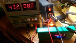
Great instructions. Unfortunately, I think I smoked the amperage readout when I first soldered it together. All it reads is 0.0, and that's with trying to adjust the amperage trim. I found some solid copper wire laying around that was 14ga, so I went off the resistance of that wire and with your formula came up with this: .00075/.002525*12=3.564"
Fail (Medium).jpg
 
That length looks right for 14g - should work fine.

But - since it doesn't.... Perhaps the eBay spec is not correct - it works but they are actually using a different shunt value (going for 'the glass is half full' outlook :) ).

Try shunt with 2-3 of feet of wire (thinner would be best (18-20g), but the present 14g is fine) and see if you get a reading. Since you have the equipment there, if it works, you can easily work down to a proper length with good calibration. If the long-wire shunt doesn't give a non-zero reading, then the meter is likely toast. If it works, then for your low current application even 20g would be just fine.

Another thing you can try since you have such low currents for a 100A meter is to build a shunt with 10x the resistance. This will trick the meter into thinking you have 10x the current which may get into a measurement range where it's happier. So - rework the equation with 10x the resistance and use a thinner gauge wire so the length is manageable. The display will read 10x higher, so....
 
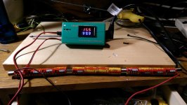
I tried a 2' piece of 14ga and came up with a few amp reading. After searching around, I came up with no solid wire of a decent gauge. I ended up using some 22 or so gauge speaker wire. I had to fiddle with the distance a little and finally settled for about 1.12". Now that I'm charging the batteries again, I noticed something odd. It's set on .9A charge but the screen bounces between .7 and 1.5'ish every few seconds. Is this normal behavior for a 'smart' charger?
Idunno (Medium).jpg
 
Excellent news.
Oddly, the length with which you ended up is exactly twice the predicted length (using 22g wire resistance from the table). This sounds suspiciously like they used a 75mv/50A shunt instead of 75mv/100A unit as stated. In the end, as long as the shunt matches the meter scaling, all is good.

In any case, glad you were able to salvage your meter and put it to use.

No help with the Smart Charger question, though.... :?

That may want a new thread title - go your first post in the thread, press 'edit', and change the title.
You now need 'Smart Charger' instead of 'shunt' folks.
 
Well done on the mod.

I'd think a wildly varying current would make the end of charge delta V or delta T measurement impossible. Maybe it is some sort of maintenance charge at the end of charge? Does it do it the whole time from empty?

Stick your multimeter on amps and connect it in series just to rule out if the panel meter is reading incorrectly.
 
Yep, its a maintenance charge of some sort. That's when I realized my calibration was a little off.. Should have left it alone. Three attempts later, I still can't get the correct length of wire. But I was trying to adjust it while it was still attached to the charger. I'll pull it out and hook it to a light bulb like before. Funny how things can go downhill so quickly when you are getting tired. Tomorrow is another day.
 
Ya - when you get down to an inch of length you're asking for a difficult time just because of % of resistance change for a small change in unit length (or solder flow).

A little heavier gauge would be better...

As an alternative (I've never actually tried this, but it should work):
you might try doubling or tripling up with roughly equal length parallel wires between the power leads and make the sense leads and adjustment in just one of them. For instance, if you double the wires to the power leads then each will carry about half the current. With the sense leads on just one of the parallel wires, the wire will need to be twice as long to double the resistance so the developed voltage will be the same as with only a single wire. This would make your 1" shunt about 2" instead and less sensitive to fabrication variations. Four wires would be about 4", etc.

Anyhow, just a thought... :D
 
brainfarth said:
Now that I'm charging the batteries again, I noticed something odd. It's set on .9A charge but the screen bounces between .7 and 1.5'ish every few seconds. Is this normal behavior for a 'smart' charger?
It might be. I have had two "bulk" Li-xx chargers that do that. One is a HiPower (highpower?) brand charger, the other I think was KingPan? Anyway, both of them cycle thru long pulses of power, with an average current of less than half of what the charger is supposedly set to/capable of. :/

I also have a Tenergy? Ni-xx charger taht looks a lot like the picture in your first link at the start of the thread, and it does that too, probably because it is testing for the Nickel-type batteries' Voltage-delta point.
 
Back
Top