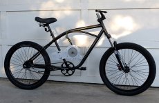
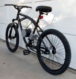
Dyno Glide - Bixby - Cruiser Cafe Racer Builds

Looks great! Elegantly simple design and it looks right at home on the frame. The chainline may prove to be challenging but from the looks of it you can switch the freewheel to the inside of the bearing plate if need be. How is the pedal clearance with the motor?
 
Thud said:
I'll chime in too Roy,
Another really clean bike!
All the tidbits you fab just look right at home.
Looking forward to your review of the motor/drive system once its been tested out for a few charge cycles.
Thanks for taking the time to document your work & letting us follow along.
T
THANK YOU!
It's my pleasure to offer this project here on ES and I hope you and others will comment and make suggestions as it goes along. This powerful community helps all projects get better and better.
 
DanGT86 said:
Looks great! Elegantly simple design and it looks right at home on the frame. The chainline may prove to be challenging but from the looks of it you can switch the freewheel to the inside of the bearing plate if need be. How is the pedal clearance with the motor?
Thanks Dan.

You are right, it's the chain lines that concern me the most at this point. I think there is not enough room on the inside of the bearing plate but will give it a try. I may have to stretch out the frame between the drop outs a bit to accommodate the chain lines...we shall see.

On the left side the crank arm just kisses the bolt that protrudes from the end of the motor. I will deal with this by getting a wider BB shaft...or may have to make my own cranks. Not sure about the right side yet because I still have to machine the timing pulleys down to 23mm +/- wide and get them fitted to the shafts.
 
If your crank is hitting just the screw on the left you could counterbore the endplate to recess the screw head flush with the plate. The threads would then stick out of the right side and need to be cut flush. That is also assuming the thread on the bolts are long enough inside there. Maybe Neptronix remembers how long they were. His teardown and measuring thread on this motor has been very insightful.

My setup requires that i make a new rear motor plate for pedal clearance. I am going to try and shorten the steel motor body and move the bearing further inboard on the shaft. That rear plate is just too thick. The width of the transmag motor has been the only downside for me.
 
yawstick said:
I've looked for information on the motor you are using and not finding much other than posts by you. Do you have a link to a source for this motor or technical details for it?
Paul
Info here on ES:
http://endless-sphere.com/forums/viewtopic.php?f=31&t=44058
http://endless-sphere.com/forums/viewtopic.php?f=30&t=50066

TransMag website:
http://www.transmag.com
 
DanGT86 said:
If your crank is hitting just the screw on the left you could counterbore the endplate to recess the screw head flush with the plate. The threads would then stick out of the right side and need to be cut flush. That is also assuming the thread on the bolts are long enough inside there. Maybe Neptronix remembers how long they were. His teardown and measuring thread on this motor has been very insightful.

My setup requires that i make a new rear motor plate for pedal clearance. I am going to try and shorten the steel motor body and move the bearing further inboard on the shaft. That rear plate is just too thick. The width of the transmag motor has been the only downside for me.
Thanks Dan.
Great ideas!
I am not so ambitious as to mod the motor!
What I get is that the rear plate is a part of the cooling system. TransMag makes a non-vented shorter version but at half the power.
 
I asked Roller about modding that rear cover and he said the fancy air intake casting had more to do with a controller that was mounted to the motor in its original application. He said a thinner cover with holes in the face would probably work just as well for cooling. I know that doesnt make modding the motor any easier but it was good to hear there were options.

As far as counter boring the bolt head spots i think the press fit of the covers in the can does most of the holding so the motor probably wont fall apart if the bolts are briefly removed. I guess without removing the cover there would be no way to know if you were about to bore through it though. I dont blame you for wanting to leave that alone.
 
DanGT86 said:
I asked Roller about modding that rear cover and he said the fancy air intake casting had more to do with a controller that was mounted to the motor in its original application. He said a thinner cover with holes in the face would probably work just as well for cooling.
Interesting!
Maybe milling or turning the cover down from the edge where it meets the steel can will allow it to become 'shorter' and still look like it belongs there. Then drill holes for air flow.
 
Its hard to say without taking it apart to see exactly what you are cutting into. A less invasive approach to moving the bearing or shortening the whole motor would be to make an end plate shaped like a top hat. This way the bearing stays in the same place on the shaft but the pedals swing past that along the thin part of the plate. It would allow the pedals to occupy the same axial space as the bearing while keeping the motor a little closer than trying to clear all 5+ inches of motor.
 
DanGT86 said:
...This way the bearing stays in the same place on the shaft...
Good point. Cutting the rim means the bearing support/bearing will also move...I am going to leave it alone and like AJ suggested allow it to protrude out of some kind of 'body work'. I will just find a way to get the pedal clearance I need.
 
More from the Dyno ebike workshop.

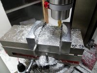
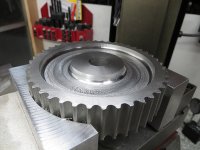
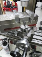
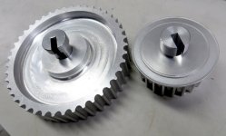
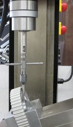
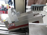
The pics are the making of sacrificial jaws for my milling vice. These sacrificial jaws are then used to hold the timing pulley for further machining.

One picture shows the making of the jaws and another indicates the timing pulley being held by the modified jaws. I used the same setup on the mill to first make the jaws and then with the timing pulley held firmly and in exactly the right place - using the rotary table to remove some excess material. The last pic shows the rotary table setup on the mill.

My first use of such a setup so the finish of the removed material will get better with time. Have to remember to lift the cutting head .003" to not mark up the horizontal surface. Also the camera shows a surface texture where a nice looking cutting pattern exists.

Making-Sacrificial-Jaws.jpgShaping-Timing-Pulley.jpgRotary-Table-on-Mill.jpg
 
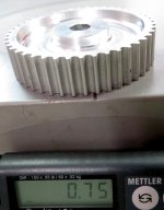
That's a pretty massive pulley! Good thing you had means to lighten it up a bit. I'm assuming that's the "big" one, at about 44t, and that the drive pulley is about 22t. That's what it looks like from the CAD images.

What version of 8mm pitch belt are you using? There's a million and one tooth profiles, but I would expect you to be using either the P8M or the (EV)8YU. And belt width? I'm most curious since I'll be doing another Transmag build soon. I've used EV5GT (5mm pitch, 9mm width) before for an RC drive experiment, but the power levels were MUCH lower and the RPM about double what yours is likely to be.

For those who are unfamiliar with MISUMI, get familiar! Awesome site to use if you don't have ready access to machining of shafts and pulleys and such, as long as you're comfortable with metric sizing. They have great belt selections, have pretty much anything available for download to CAD, and, perhaps most importantly, very good documentation on specs. Here's their pulley/belt specification sheet: http://us.misumi-ec.com/pdf/fa/2010/p3515-3536.pdf

Assuming a EV8YU belt, 20 mm wide, your design power handling is about 6kW continuous, so you should be good with the TransMag. It does put that in the sort of 'questionable life' region of the chart because your RPM is high and the small pulley tooth count is so low, but for an eBike (as opposed to industrial equipment) the life you'll get will probably be very good.

Looking forward to more updates!
 
Also, you haven't decided on a final voltage yet, right? Assuming 44t-22t pulleys (2:1), and what looks like 20t-60t sprockets (3:1), your overall reduction should be 6:1, which seems perhaps a little tall in the gearing department.

50V battery from em3ev would give about 3600rpm decently loaded, or 600 rpm. 24" wheel ---> 42mph before aero drag

75V battery would be 63mph (!) before aero drag, which would obviously be a bit extreme.

You have this battery highlighted (50V 16.5AH Samsung cells) : http://em3ev.com/store/index.php?route=product/product&path=35&product_id=134

But it can only do maybe 40A (30 recommended), but the 'dyno' charts show the motor not reaching saturation til 60A min perhaps 80A max. To keep the your rpm DOWN but keep the power UP, what about 50V 20AH A123?: http://em3ev.com/store/index.php?route=product/product&path=35&product_id=106

You'd get 50V 60A continuous output, for the 3kW+ rating they give the TransMag, and the cost is in the middle of your previous 50V and 75V selections.

Personally, I'll probably be using either QTY2 50V 15AH Pings I have from a previous project (for 30AH about 50A safely), or I'll pony up and buy some Headway action for 75V fun if I can bring the RPM down enough.

Good luck...
 
ttobiassen said:
...For those who are unfamiliar with MISUMI, get familiar! Awesome site to use if you don't have ready access to machining of shafts and pulleys and such, as long as you're comfortable with metric sizing. They have great belt selections, have pretty much anything available for download to CAD, and, perhaps most importantly, very good documentation on specs. Here's their pulley/belt specification sheet: http://us.misumi-ec.com/pdf/fa/2010/p3515-3536.pdf
Thanks for your MISUMI lead, it's an interesting site with many options - but I spent over an hour with a MISUMI rep, who was very nice and patient, and the upshot was that for 8mm pitch all they had were pulleys with a 20mm bore - which was just too large for my needs. But I do think this is a great site for people who need off the shelf solutions or special shaft machining needs.

For standard pulleys and belts take a look at http://pfeiferindustries.com - they sell 8mm pulley stock, and other goodies, at reasonable prices. For sure Pfeifer is where I will go in the future.
 
ttobiassen said:
Also, you haven't decided on a final voltage yet, right? Assuming 44t-22t pulleys (2:1), and what looks like 20t-60t sprockets (3:1), your overall reduction should be 6:1, which seems perhaps a little tall in the gearing department.
At 48v the above gives me about 40mph with 18t-48t sprockets. I just put on what I had on hand for the build in progress.

ttobiassen said:
50V battery from em3ev would give about 3600rpm decently loaded, or 600 rpm. 24" wheel ---> 42mph before aero drag
I usually put in a .8 efficiency loss factor up front when I calc performance and speed. With a .8 EF and 48v I get a motor rpm of 2980 and (22t-44t and 18y - 48t) I get just about 40mph.

ttobiassen said:
75V battery would be 63mph (!) before aero drag, which would obviously be a bit extreme
Not going there. Gotta gear down to a more reasonable speed of say 45-50mph at 72v...

ttobiassen said:
You have this battery highlighted (50V 16.5AH Samsung cells) : http://em3ev.com/store/index.php?route=product/product&path=35&product_id=134

But it can only do maybe 40A (30 recommended), but the 'dyno' charts show the motor not reaching saturation til 60A min perhaps 80A max. To keep the your rpm DOWN but keep the power UP, what about 50V 20AH A123?: http://em3ev.com/store/index.php?route=product/product&path=35&product_id=106

You'd get 50V 60A continuous output, for the 3kW+ rating they give the TransMag, and the cost is in the middle of your previous 50V and 75V selections.
Thanks for this - very helpful!
 
More in-progress photos coming next week.

Built the 24" wheels and installed the tires.

Cold set the frames to widen the dropouts to fit the wider rear hubs. Gotta love steel for easy frame mods! I used the all-thread method to open up the frame between the dropouts. Important when stretching the frame to keep the dropouts centered in the frame. Sheldon Brown has a great string method for keeping track of this. Also important is to keep the dropouts parallel or unwanted forces will be introduced into the axle.

I realized I need to move the final drive freewheel inbound of the bearing plate and move the baring plate about 3/8" further away from the bike center line to get the final drive chain line where it needs to be. I knew that there would be some fussing to get the chain line right - so this is a relatively easy adjustment and easy spacer to make.

Got suspension forks mounted on the Bixby, you may recall that this is a 2 bike build thread - but pics of the Bixby have not shown up yet. Hopefully I will have pics of the Bixby early next week.

Have to do something trick to get disc brake calipers mounted for the rear brakes. I also have to go to 8" discs at the rear so the calipers will clear the hub that holds the rear sprocket.

Really thinking hard about ordering controllers and a battery.
 
The purchased steel broach bushing for the 44t pulley is for a standard 5/8" shaft...because I am only going to broach very few 15mm motor shaft key-ways I decided to make one for this application out of aluminum for the 22t pulleys.
I will machine the 5mm key stock to fit the 3/16" key. It will be 5mm (0.197") at the motor shaft and 3/16" (0.188") at the pulley.broach-bushings.jpg
 
spinningmagnets said:
Awesome work, Roy!...as usual...
Thanks spinningmagnets, I really appreciate your support and kind words.

Here's the deal. I stress over every part. While I do have an aptitude for this kind of thing - every part I make involves one or more operations that I have never done before. It may look like I have a machine shop background but that is not the case. After the first Cortina build and paying a machinist to make the drive system - I decided to learn to make what I needed myself. Sure I buy stuff like timing pulleys and other stuff I need but mostly for the custom stuff I make it myself. I took machining classes at the local Community College to get me going and I have a few machinist friends that make it all possible. It's a team effort. But again, it's not easy - it's a lot of work - but it's gratifying and worth every second. Today, after spending most of the afternoon in the shop, I realized that I wish I had had the confidence earlier in life to explore and pursue my maker side.

Probably too much information for most of you...
 
Back
Top