sigimem
100 W
Very nice build. Aluminium panels look good and wiring is very clean. what contactor did you use for the main power?
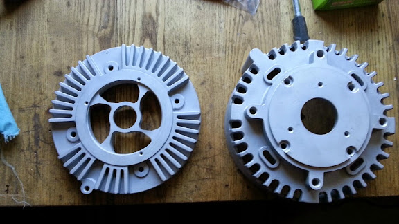
The sprockets seem wrong to me they look like ones that were worn out
The sprockets seem wrong to me they look like ones that were worn out