JCG
100 W
- Joined
- Nov 10, 2008
- Messages
- 174
I'd posted on this project (conceptually) a few times in the past, and recent conversations (and PMs) have convinced me that it's time to start a thread outlining what's been going on with a project I'm dividing my time into: conversion of a General Motors EV-1 into a serial hybrid with an ultracapacitor-only electrical storage buffer. Primary energy is to be from a small (25-35 kW) genset which will charge the caps, and the standard EV-1 drivetrain (with a repaired controller) and its 103 kW motor. The car has been here since before I arrived (since 2002), but only recently we've been granted a place to work on it. Here are some photos to get started explaining the project.
The car is in a small fenced-off area in our University's service center (basically a parking garage with some shop equipment that I'm not allowed to use):
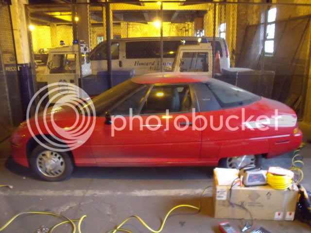
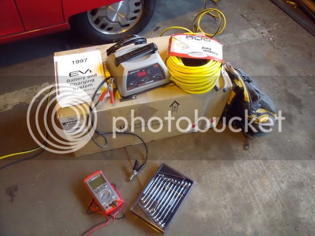
These are the immediate tools of the trade. The cardboard box contains the repaired and refurbished motor controller/inverter, which is the biggest key to the whole project. It will accept a DC input voltage range of 200-400 V and is controlled with throttle and braking pots (5 kohm). I'll open the box up once I'm ready to start turning the wheels. For now, I need to work on the 12 V system and getting the caps installed.
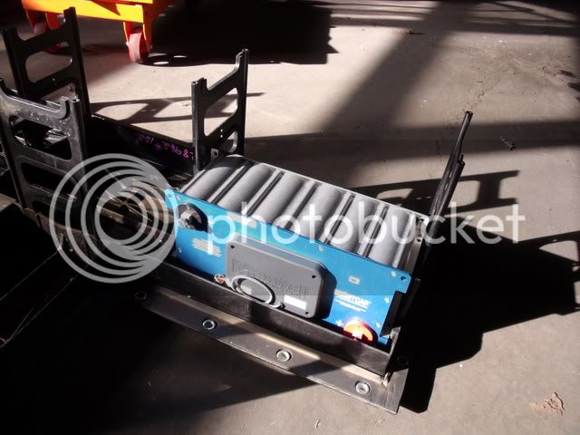
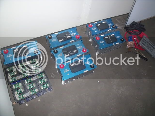
Here are the cap modules. Eight total, each 48.6 V and 165 F which will provide a 389 V, 20.6 F series pack. The generator will charge these to about 375 V, leaving head space for regen braking when they are fully generator-charged. Two of the packs I've assembled myself, the other six were purchased as you see them.
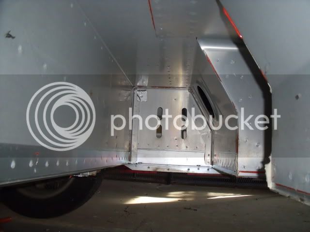
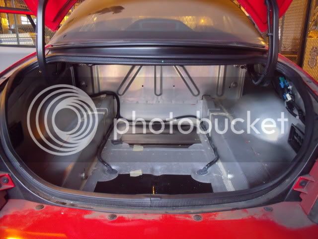
Here's the trunk space, in which I hope to fit some kind of ICE and generator pair. It's a deep trunk, but not a tall trunk. That will be an interesting design.
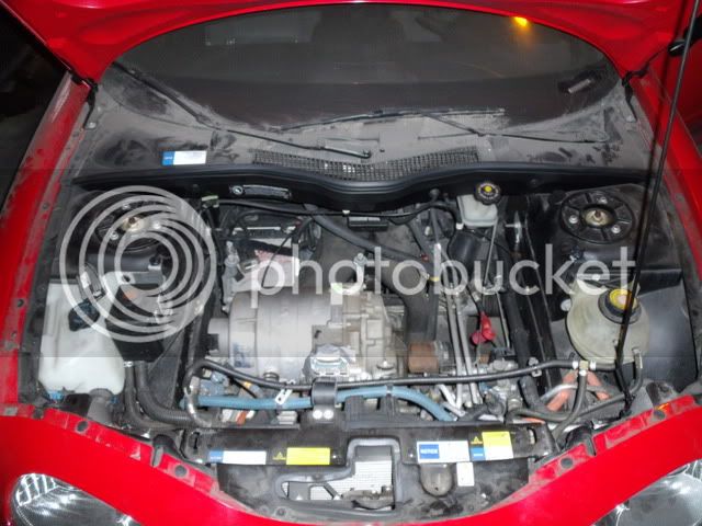
Here's a look under the hood, and a close-up of the motor. The motor is usually concealed underneath the inverter, which is mounted above it when installed.
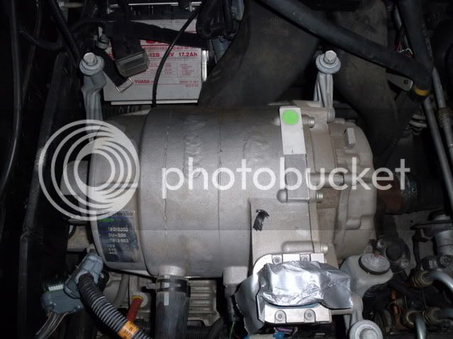
Here's the small 12 V auxiliary battery, which is kept charged with the DC-DC converter mounted alongside the inverter. The battery had sat around for several years, and was a lost cause.
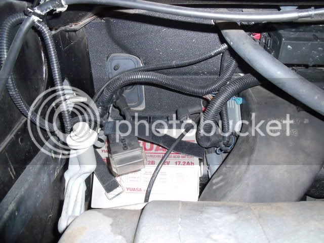

I replaced that battery and charged it in place.
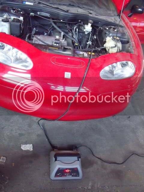
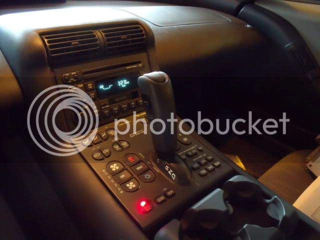
Supplying the charging voltage to the 12 V bus allowed me to test the vehicle's auxiliary systems. I cracked the startup code and got the radio, lights, and dash working.


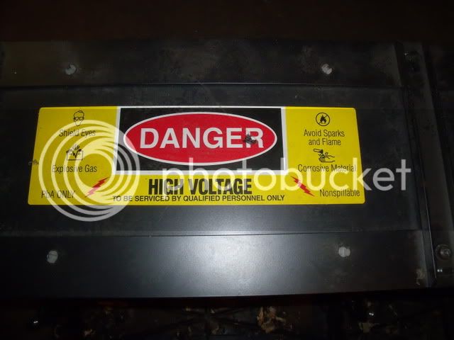
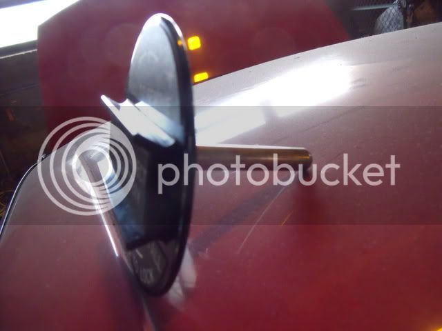
One interesting item is the high-voltage service disconnect which was in the cabin. It's basically a pin that was used to connect the series of VRLA batteries that the car used before you'd take out the battery tray. Here's a photo of it sitting on the roof.
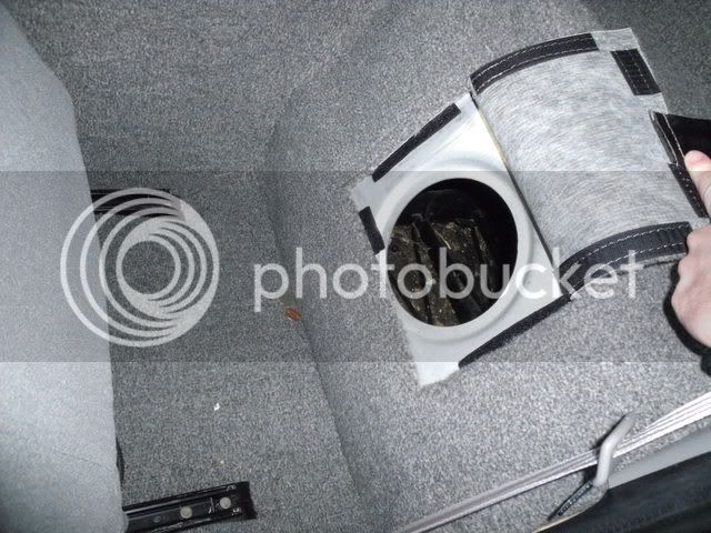
The disconnect is supposed to be placed behind the driver's seat. Here's the flap. When I opened it, there was just an empty space behind it rather than an electrical fixture.

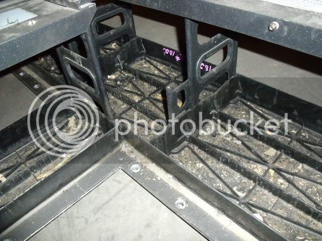
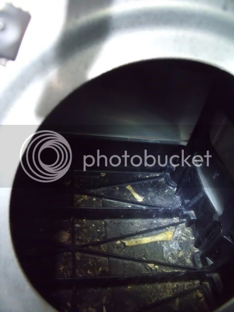
Inside: rat manure and chicken bones, which they had dragged up inside the car to eat at their leisure. Cleaning the battery tray out is going to be a pleasure.
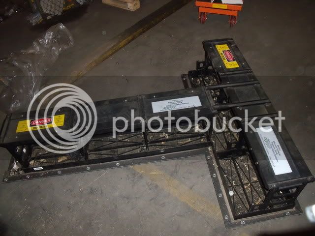
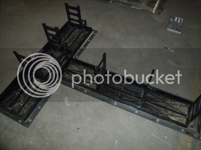
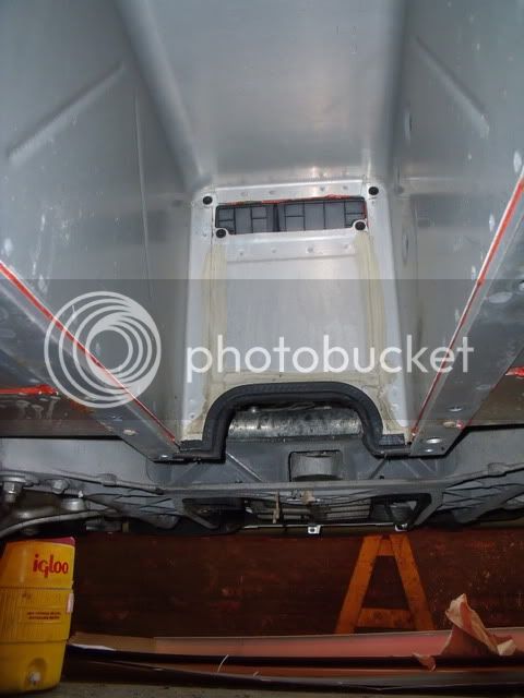
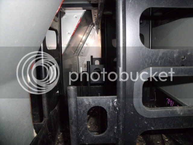
Here's a view inside the T-shaped tray. All the VRLA batteries have been removed. This is now the space that I'll use to house the ultracaps. There should be plenty of room.
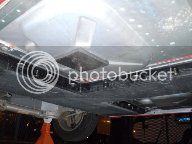
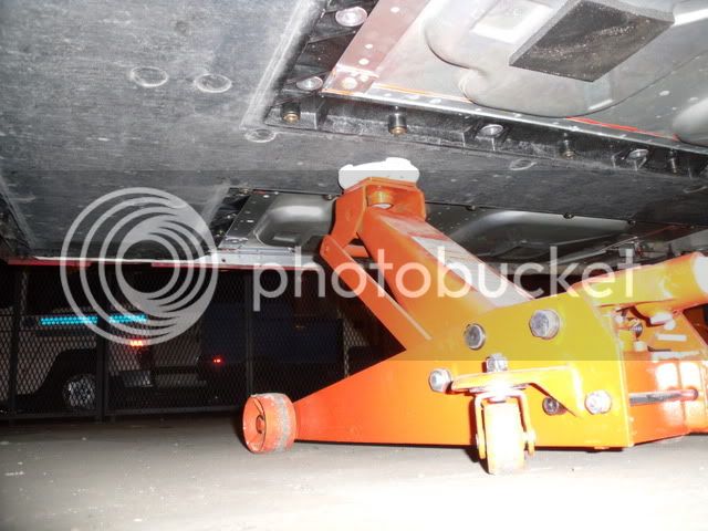
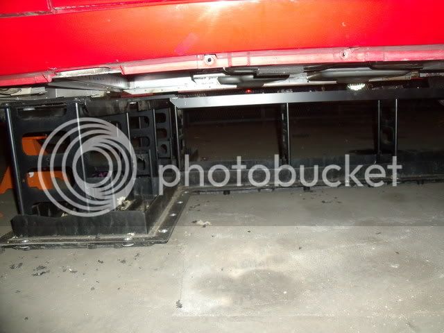
The battery tray, which I mentioned is T-shaped, drops out from underneath the car. I needed to get the car on jack stands (no lift available) and will drop the tray out after removing all the bolts. Getting any vehicle up on four jack stands is a scary job to do by one's self, especially with only one floor jack to use.
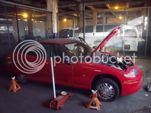
Luckily, I found a method that worked and should be in good shape to drop out the tray soon.
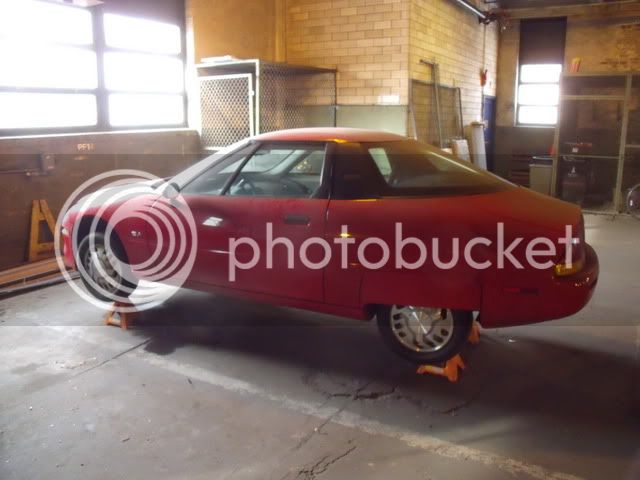
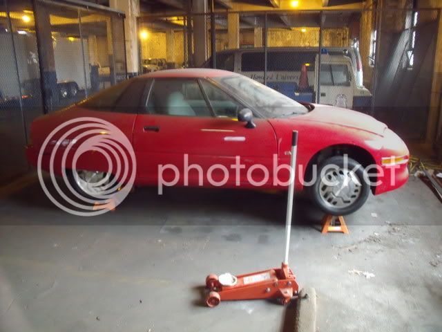
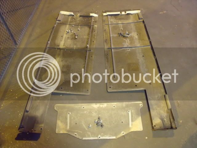
I'm now float charging the auxiliary battery and the next step will be to drop out the tray, clean it, and see what electrical connectors still exist down there. Once I know that, I can re-install the controller and DC-DC converter, then charge the caps up from a rectified 220 VAC source (300 +VDC with capacitor storage) to light up the car and hopefully spin the wheels. It's baby steps for now, but exciting stuff.
The car is in a small fenced-off area in our University's service center (basically a parking garage with some shop equipment that I'm not allowed to use):

These are the immediate tools of the trade. The cardboard box contains the repaired and refurbished motor controller/inverter, which is the biggest key to the whole project. It will accept a DC input voltage range of 200-400 V and is controlled with throttle and braking pots (5 kohm). I'll open the box up once I'm ready to start turning the wheels. For now, I need to work on the 12 V system and getting the caps installed.

Here are the cap modules. Eight total, each 48.6 V and 165 F which will provide a 389 V, 20.6 F series pack. The generator will charge these to about 375 V, leaving head space for regen braking when they are fully generator-charged. Two of the packs I've assembled myself, the other six were purchased as you see them.

Here's the trunk space, in which I hope to fit some kind of ICE and generator pair. It's a deep trunk, but not a tall trunk. That will be an interesting design.

Here's a look under the hood, and a close-up of the motor. The motor is usually concealed underneath the inverter, which is mounted above it when installed.


Here's the small 12 V auxiliary battery, which is kept charged with the DC-DC converter mounted alongside the inverter. The battery had sat around for several years, and was a lost cause.


I replaced that battery and charged it in place.

Supplying the charging voltage to the 12 V bus allowed me to test the vehicle's auxiliary systems. I cracked the startup code and got the radio, lights, and dash working.


One interesting item is the high-voltage service disconnect which was in the cabin. It's basically a pin that was used to connect the series of VRLA batteries that the car used before you'd take out the battery tray. Here's a photo of it sitting on the roof.

The disconnect is supposed to be placed behind the driver's seat. Here's the flap. When I opened it, there was just an empty space behind it rather than an electrical fixture.


Inside: rat manure and chicken bones, which they had dragged up inside the car to eat at their leisure. Cleaning the battery tray out is going to be a pleasure.

Here's a view inside the T-shaped tray. All the VRLA batteries have been removed. This is now the space that I'll use to house the ultracaps. There should be plenty of room.

The battery tray, which I mentioned is T-shaped, drops out from underneath the car. I needed to get the car on jack stands (no lift available) and will drop the tray out after removing all the bolts. Getting any vehicle up on four jack stands is a scary job to do by one's self, especially with only one floor jack to use.

Luckily, I found a method that worked and should be in good shape to drop out the tray soon.


I'm now float charging the auxiliary battery and the next step will be to drop out the tray, clean it, and see what electrical connectors still exist down there. Once I know that, I can re-install the controller and DC-DC converter, then charge the caps up from a rectified 220 VAC source (300 +VDC with capacitor storage) to light up the car and hopefully spin the wheels. It's baby steps for now, but exciting stuff.


