Experiment of charge/discharge of LFP battery pack. How to connect BMS?

francuscus

1 µW
Joined
Jan 15, 2025
Messages
3
Location
Santiago, Chile
Hello, community. I’ve been getting involved in the topic of BMS (Battery Management Systems) and their role in determining the state of charge (SoC) of LFP-type batteries. Perhaps someone here has experience with how to use a BMS for testing batteries. I’ve been conducting charge and discharge experiments and HPPC tests (pulse tests to obtain the dynamic properties of the battery). So far, I’ve done this without a BMS.

What I want to do now is perform the same experiments using a BMS to monitor my battery pack and see what SoC estimate it provides during these experiments.

My question is about how to connect the BMS if I want to obtain voltage and SoC data through it. I’m attaching an image of my setup. Currently, I have a set of batteries connected to a programmable power supply and, in parallel, to an electronic load. This allows me to charge and discharge the batteries by turning the power supply and electronic load on and off as needed. However, I’m unsure where the BMS should be connected. Should it be connected in parallel with the batteries, the power supply, and the load? Or should it be connected in series with the batteries?

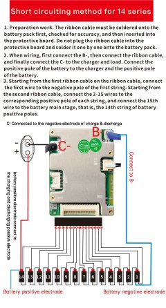
I’ve seen diagrams of JBD BMS units showing a -B terminal that should be connected to the overall negative terminal of the batteries and a -C terminal that should go to the negative terminal of the charger. From this, I understand that the BMS should be connected in series with the battery pack and the charger. But my question about this is: will the current flow through the BMS? Wouldn’t this damage the BMS if I’m charging the batteries with a very high current?
 

Attachments

  • montajex.png
    montajex.png
    221 KB · Views: 2
Hello, community. I’ve been getting involved in the topic of BMS (Battery Management Systems) and their role in determining the state of charge (SoC) of LFP-type batteries.

The BMS doesn't usually do anything to determine SoC; it doesn't care. All most BMS do is monitor each cell for voltage, and may also monitor the difference in voltage between cells. Then it turns the output of the pack on or off based on what it actually reads on each of those voltages vs the limits programmed into it (or built in as hardware for "dumb" BMS; these are much less common nowadays but still exist).

Some "smart" BMS may monitor current in and out of the BMS and do coulomb-counting to keep track of SoC; these would need to be calibrated to that particular battery at the original build time, and probably recalibrated periodically over time.

Some "smart" BMS just track either total pack voltage or the average cell voltage x number of cells for a guesstimate of total pack voltage, and use that with some data table to guess the SoC to display on an app / etc.

If you want to use a BMS to monitor SoC for you, you'll need to determine exactly how that BMS is doing it, to be sure it is giving you the *actual* SoC, and that it's calibrated to the cells it's monitoring (if it has that option--if not, it's likely to be inaccurate over time, if not immediately).


Perhaps someone here has experience with how to use a BMS for testing batteries. I’ve been conducting charge and discharge experiments and HPPC tests (pulse tests to obtain the dynamic properties of the battery). So far, I’ve done this without a BMS.
What, specifically, do the tests actually do, electrically?

If you have high current pulses, the BMS has to be designed to handle those pulses, or you may damage or destroy it.
Same if you have high voltage pulses.


My question is about how to connect the BMS if I want to obtain voltage and SoC data through it.
BMS are connected to the cells the same way regardless of whether they provide SoC or not--however that specific BMS's wiring instructions indicate to do so.

BMS are connected to any load (tester or controller, etc) or charger the same, regardless of whether they provide SoC or not--however that BMS's wiring instructions indicate to do so.


Typical external connections on a BMS include C- (charge negative), P- (discharge negative) and B- (battery negative at the cell block). Some combine the C- and P-, so both discharge and charge go thru the same point.

You'll need to pick the type you want to use, and wire appropriately for that type.


But my question about this is: will the current flow through the BMS? Wouldn’t this damage the BMS if I’m charging the batteries with a very high current?

If the current doesn't go thru the BMS, the BMS cannot do it's job of monitoring the pack and disconnecting it from any load or charge source when it detects a condition outside it's limit.

You must use a BMS capable of whatever you are going to put the pack thru (I'd recommend something with much better specs than you need, so that you have a safety margin to avoid failures, as the manufacturers of these parts don't generally include much, if any safety margin, and typically advertise things right up at their actual failure-edge limits. (also often true of the actual components as well as the assemblies they're in)

Additionally, make sure the cells you use are designed to charge at the rate you're using--if not, you could damage them in a way that could lead to a fire. (regardless of chemistry)
 
First, I thank you for your time to answer my questions. About yor comments...

The BMS doesn't usually do anything to determine SoC; it doesn't care. All most BMS do is monitor each cell for voltage, and may also monitor the difference in voltage between cells. Then it turns the output of the pack on or off based on what it actually reads on each of those voltages vs the limits programmed into it (or built in as hardware for "dumb" BMS; these are much less common nowadays but still exist).

Some "smart" BMS may monitor current in and out of the BMS and do coulomb-counting to keep track of SoC; these would need to be calibrated to that particular battery at the original build time, and probably recalibrated periodically over time.

Some "smart" BMS just track either total pack voltage or the average cell voltage x number of cells for a guesstimate of total pack voltage, and use that with some data table to guess the SoC to display on an app / etc.

If you want to use a BMS to monitor SoC for you, you'll need to determine exactly how that BMS is doing it, to be sure it is giving you the *actual* SoC, and that it's calibrated to the cells it's monitoring (if it has that option--if not, it's likely to be inaccurate over time, if not immediately).
I've got a 100A BMS (My cells are LFP 56Ah) and connected it via Bluetooth to the XiaoXiang app. Indeed, the app gives me the voltage records of each cell and the maximum difference between them and also gives me a percentage of charge of the cells. I understand that the SoC is something that cannot be known for sure and that the application must have its own way of calculating it. Either based on the coulomb counting method or on the relationship of the voltage with the different SoC levels (10%, 20%, 30%...) which can be configured manually in the app; or in a combination of both. This is my assumption, since I have not found information in the technical sheets of the BMS or the app.


What, specifically, do the tests actually do, electrically?

If you have high current pulses, the BMS has to be designed to handle those pulses, or you may damage or destroy it.
Same if you have high voltage pulses.
The tests I am doing consist of fully charging the battery (up to its maximum operating voltage) and applying short discharge and charge pulses at different charge levels, recording the voltage response to the application of these pulses. What I plan to do with this is create a representative model of the battery based on the experimental results. In these tests I do not use current of more than 20A and these are applied for a few seconds, except when I want to reduce the load level by a certain percentage. In that case, it applies a current of lower amplitude for a long time.


BMS are connected to the cells the same way regardless of whether they provide SoC or not--however that specific BMS's wiring instructions indicate to do so.

BMS are connected to any load (tester or controller, etc) or charger the same, regardless of whether they provide SoC or not--however that BMS's wiring instructions indicate to do so.


Typical external connections on a BMS include C- (charge negative), P- (discharge negative) and B- (battery negative at the cell block). Some combine the C- and P-, so both discharge and charge go thru the same point.

You'll need to pick the type you want to use, and wire appropriately for that type.
I am now attaching an image with the connections that must be made according to the BMS manufacturer.


If the current doesn't go thru the BMS, the BMS cannot do it's job of monitoring the pack and disconnecting it from any load or charge source when it detects a condition outside it's limit.

You must use a BMS capable of whatever you are going to put the pack thru (I'd recommend something with much better specs than you need, so that you have a safety margin to avoid failures, as the manufacturers of these parts don't generally include much, if any safety margin, and typically advertise things right up at their actual failure-edge limits. (also often true of the actual components as well as the assemblies they're in)

Additionally, make sure the cells you use are designed to charge at the rate you're using--if not, you could damage them in a way that could lead to a fire. (regardless of chemistry)
I think my questions lie in:
- Would I have problems if I charge or discharge the batteries with the connection scheme proposed by the BMS?
- Would it hold up to the charge and discharge current levels (BMS is 100A, applied current <20A)?
- If at any time the battery voltage reaches a lower or higher value and the protections are activated, would the BMS cut off the entire circuit?
 

Attachments

  • Conexiones.jpg
    Conexiones.jpg
    201.7 KB · Views: 1
I think my questions lie in:
- Would I have problems if I charge or discharge the batteries with the connection scheme proposed by the BMS?
Per the diagram, that is what they call a "common port" BMS, meaning boht C- and P- are the same point; the FETs the BMS uses to switch the pack's external connection on/off are all wired to that point (normally in series).

This means that as long as the BMS has turned on both charge and discharge functions (no limits engaged), the FETs are all on, and it's essentially a low-resistance switch.

If for any reason the BMS turns one of the functions off but not the other, then the one that is off doesn't act as a switch, it acts as a diode, blocking the current path that it's for, and allowing the other current path *but* with a voltage drop across it that causes significant heating at high enough currents. Not typically something you have to worry about when using them within their limits, but that's how they would function in that event.

(sometimes a smart BMS that uses a common port will lock up or enter some fault condition that turns off BOTH directions, and then you can't recharge it or discharge it to correct an excursion beyond LVC or HVC until the BMS is reset. That reset function varies between designs, so you'd have to check the documentation (if any) for what to do if it ever enters this "stuck" condition. )


In a separate-port BMS, with separate C- and P- connections, the FETs are wired separately, so don't affect each other's current paths regardless of conditions.


- Would it hold up to the charge and discharge current levels (BMS is 100A, applied current <20A)?
If your usage is well within the limits of the device, then there's no typical reason to expect a failure.

If it's a poorly designed device (PCB layout/etc issues), or uses problematic parts (counterfeit, lower-spec'd than called out, etc), then it could fail even in "normal" usage--but this is unlikely at a rate that much lower than the limits.

- If at any time the battery voltage reaches a lower or higher value and the protections are activated, would the BMS cut off the entire circuit?
That's what should happen, yes. It will turn off the FETs that allow current to pass thru the C- connection in the direction of the function the limt is for.

So if it hits HVC while charging, it would turn off the charge FETs.

So if it hits LVC while discharging, it would turn off the discharge FETs.
 
Back
Top