LFP,
I love your passion for the "real deal" with the physics. We get educated and entertained all at once.
After reading every post on this cogging thing, after applying some of my own engineering background, and after riding the very motor being questioned for 4 months, I will say this:
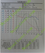
Falco-motors is claiming a zero resistance when you start to pedal, unassisted, and that effect is a low cogging torque. It is true, there is zero noticeable motor resistance when starting out. From the cogging torque graph, it makes sense that these windings are balanced, the areas equal, and amplitude smaller than the 3-ph results. There is low (initial) force against the legs.
When riding down the road at 10-15mph, then yes, your point about the core loss being the drag on a dd motor, is true Experience wise, the Falco motors free wheels well, but not 100% without core loss drag, and not even close to what a Bionx feels like. (much worst) It is more noticeable when at high speeds, over 30 mph and I stop pedaling and coast.
I resisted DD motors for years because of the expected drag making it less of a bike like feel. So I was sold on the Falco PR.") and tried it. Overall very happy with the performance of the 500W hub - just wish it weighed 2.5lb! don't we all.
and tried it. Overall very happy with the performance of the 500W hub - just wish it weighed 2.5lb! don't we all.
So I hope you get to check one out and let us know what you find. Once I got my hub re-programmed, the pedelec mode was a hoot and the system put out good power.
Bike_On
PS . You stated many times that 3-ph motors "can" approach 98% eff. That seems to imply that only the really well design hubs, not the majority, run at 98%. True? Is there a typical eff range for 3-ph hubs? How will that compare to the average Falco 5-ph? I know you are challenging the PR hype, but I want to make sure you aren't using your knowledge of the limits to generalize to the masses.
I love your passion for the "real deal" with the physics. We get educated and entertained all at once.
After reading every post on this cogging thing, after applying some of my own engineering background, and after riding the very motor being questioned for 4 months, I will say this:
Falco-motors is claiming a zero resistance when you start to pedal, unassisted, and that effect is a low cogging torque. It is true, there is zero noticeable motor resistance when starting out. From the cogging torque graph, it makes sense that these windings are balanced, the areas equal, and amplitude smaller than the 3-ph results. There is low (initial) force against the legs.
When riding down the road at 10-15mph, then yes, your point about the core loss being the drag on a dd motor, is true Experience wise, the Falco motors free wheels well, but not 100% without core loss drag, and not even close to what a Bionx feels like. (much worst) It is more noticeable when at high speeds, over 30 mph and I stop pedaling and coast.
I resisted DD motors for years because of the expected drag making it less of a bike like feel. So I was sold on the Falco PR.
and tried it. Overall very happy with the performance of the 500W hub - just wish it weighed 2.5lb! don't we all. So I hope you get to check one out and let us know what you find. Once I got my hub re-programmed, the pedelec mode was a hoot and the system put out good power.
Bike_On
PS . You stated many times that 3-ph motors "can" approach 98% eff. That seems to imply that only the really well design hubs, not the majority, run at 98%. True? Is there a typical eff range for 3-ph hubs? How will that compare to the average Falco 5-ph? I know you are challenging the PR hype, but I want to make sure you aren't using your knowledge of the limits to generalize to the masses.