• Hello ES! We could use some help to get us past the finish line on building the new knowledgebase for the forum.
    Can you donate? Please see our fundraising page. Thank you!

FarGrin -- Time to push some amps

No progress on the battery yet; likely not till the weekend.

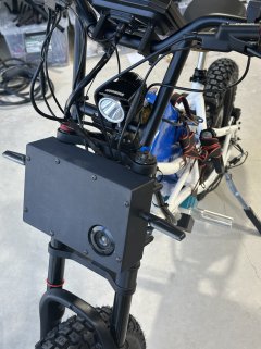
Modeled up a bracket for the display and mounted it:

Screenshot 2025-09-05 at 3.23.02 PM.png IMG_3890.HEIC_compressed.JPEG IMG_3889.HEIC_compressed.JPEG

I'm wiring in an LTE-GPS unit as well. You directly connect it to constant battery, and you also wire it to a positive voltage when the vehicle is "on". With the active/inactive state knowledge, the unit can slow down updates, activate a "bump alert" text alarm, and since the little unit has a built in battery, can even text me when the battery gets disconnected. When it goes active, it picks up GPS faster and stops the "theft" notices. (Technically, it also has a relay you can activate remotely allowing you to do something like apply the high/low brakes if it's stolen and still connected. Neat.)

Now, while the voltage range on the device is awesome (9-100v), it's just a bit shy of the battery voltage for the bike (110v). First I tried to salvage a 120v AC wall wort into this role, which did step down the 110v DC power to 12v...but it also created an isolate ground. This means when the bike's primary DCDC turns on and provides 12v to the accessory wire on the unit, the unit can't get a voltage reading from the ground for power and this unconnected 12v. Learned something new though!

So I picked up an itty bitty dcdc step down that can handle up to 120v and steps down to 12v (the battery charged will be about 110v) with a more common buck converter keeping the same ground.

Screenshot 2025-09-05 at 3.20.16 PM.pngScreenshot 2025-09-05 at 3.20.28 PM.png

Just model pictures -- I installed it before snaps.

IMG_3887.HEIC_compressed.JPEG

IMG_3891.HEIC_compressed.JPEG IMG_3888.HEIC_compressed.JPEG IMG_3892.HEIC_compressed.JPEG

Wired up the brake inputs so that they trigger the brake high while supplying 12v to the rear light for active braking lights. Configured some very basic regen tuning in the app.

And... well, aside from the battery, that's all the wiring! I zipped in all the screws, completed another bench test, strapped down the battery (literal ratchet strap) and took it out for a mild test ride around the block.

So far, no (unexpected) issues!

Speedo needs tuning, and I've got it so underpowered right now that modes 1 & 2 just give up trying to move while I'm on the bike -- but I expected that because I've got it severely constrained since I wasn't sure what the battery specs were.

I'm not sure I'll stick with the suspension seat post, between the front and rear already being there, a 3rd source of bounce feels...odd.

Lots of wire routing to clean up and sleeve, cockpit adjustments to make, and the battery to wrap up, but coming along without any major hiccups.

Right now I'm recharging the battery (very low @ 66v) so I can re-tune the controller and give it some actual pep, but this battery clearly not meant for the bike, lol.
 
Do you have a link for that LTE/GPS device?

Sure! 4g Smart Real Time Location Tracking Gps Tracker With Overspeed Alarm Wide Application To Keep Cars Safety By Cut Off Oil&power - Buy 4g Smart Gps Tracker real Time Location Gps Tracker gps Tracker Keeping Universal Cars Safety By Cut Off Oil Or Power Product on Alibaba.com

You need a SIM card to give it network access, the cheapest I could find was $5/mo. with Tello Mobile | The mobile carrier you deserve

The server it normally sends data to is hosted one somewhere in who-knows-land. If you're not super paranoid about location data, that would probably work fine. What's really cool is you can reconfigure it to report to any server, and there's a great open source project called Traccar which you can self-host to go full private (or host with them instead).

I've installed these on bikes and in cars and I'm 100% happy with them.

I saw a CarPlay unit for motorcycles.
Yeah, I especially like the ones which have live rear cameras with built-in with recording as well. However, I've yet to find one that beats a mirror (poor refresh rate, bad quality video, poor screen, or sometimes a combo of wide angle lens screen size make details really tiny, etc).
 
Ahh. Ok. I’ve seen those GOS units. Was thinking of getting one for when the kid starts driving. Is battery draw an issue? I had a scooter alarm wired in and it drained about .5v in a couple of days. I took it out.
 
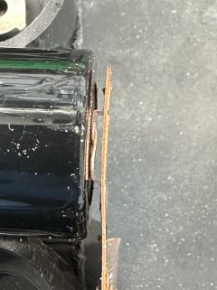
I’m really glad I paid attention to my fellow-in-amps, this torque arm was well on its way to catastrophe:

IMG_3893.jpeg
Now… pretty sure I didn’t install it bent like that!

IMG_3896.jpeg

Looks like the torque caused the clamping system to rotate around the frame stay, bending it inwards.

Fortunately, the brake rotor started colliding with this to, very loudly, inform me that I was in trouble.

I don’t know exactly what value this was at, somewhere north of 100 phase amps.
 
I’m really glad I paid attention to my fellow-in-amps, this torque arm was well on its way to catastrophe:

View attachment 376907
Now… pretty sure I didn’t install it bent like that!

View attachment 376908

Looks like the torque caused the clamping system to rotate around the frame stay, bending it inwards.

Fortunately, the brake rotor started colliding with this to, very loudly, inform me that I was in trouble.

I don’t know exactly what value this was at, somewhere north of 100 phase amps.
Something familiar going on here.
 
I mean, to be fair, this TA attachment system isn't designed (or likely tested) at anywhere near these phase amp specs. I'm on the path to sacrificing the kickstand mount. Going to go a bit harder than "drill a hole in it and hope" though. Will require a few days to get the piece right and then who knows how long to get it machined.
 
Here's the plan:

Screenshot 2025-09-06 at 6.26.22 PM.pngScreenshot 2025-09-06 at 6.26.35 PM.pngScreenshot 2025-09-06 at 6.26.52 PM.pngScreenshot 2025-09-06 at 6.27.07 PM.png

Fully capture the TA "fork fingers" and lock the assembly to the kickstand tab.

The odd little divot on the back is to account for the brake caliper:

Screenshot 2025-09-06 at 6.29.01 PM.png

I'm also debating having an m5/m6 hole slapped on the bottom so I can compress the TA fork fingers into the piece, like here:

Screenshot 2025-09-06 at 6.33.50 PM.pngScreenshot 2025-09-06 at 6.34.00 PM.png


(Side note: I think this assembly would even still allow for the kickstand if I drill out the m6 threads in the kick, mount it "outside", and just pass bolts through. I'm not sure I want to "risk" that, but we'll see how I feel as this goes.)
 
I'm not an engineer. But I noted that the arm is *twisting*. Will this bracket counter the twist in any way?
The other one was twisting because that was the axis it was attached to with just, well, the pipe clamp friction.

The above should be constrained to up and down, plus it’ll be bolted on to both of the kickstand bolt-holes. If this shears off, it’s taking the whole frame apart.
 
Is it not better to have an arm to the pivot point that meets the torque arm?
I mean, now you have the ability to get the twisting away from the swing.
 
So now that you have the TA on the inside of the kickstand mount, can't you still now put the kickstand back in place and utilize it?
Most of the kickstands I have mount "behind" (inside the frame) the kickstand tab and have the threaded holes, such that the tab is just through-holes. That's why I was saying I could drill out the kickstand threads and then mount it to the outside of the tab now instead.

Is it not better to have an arm to the pivot point that meets the torque arm?
I mean, now you have the ability to get the twisting away from the swing.
Not sure I follow what you're illustrating.
 
This build is on a bit of a pause.

Started welding the battery and realized I needed to figure out part placement and a case.

IMG_3903.HEIC_compressed.JPEGIMG_3905.HEIC_compressed.JPEGIMG_3911.HEIC_compressed.JPEGIMG_3910.HEIC_compressed.JPEG

These premade nickle/copper strips are as awesome as I'd hope they would be. Zero issues with them. (I ran the welds a smidge hot, but better than weak.)

So, why the pause?

The original plan has me using an ANT bms, a momentary-switch-with-resistor for precharge, wire ports, (maybe) a display, and a full size dc breaker all jammed in to make this battery complete. That was proving...difficult to squeeze in.

At the same time, I've been mulling over the controller choice -- I'm not super happy with the Fardriver. While it works just fine, configuring it, working with it, and trying to understand it are...easily the worst thing I've worked with. Yeah, it's powerful and relatively cheap, you can also get a basic setup working pretty quick -- but after that it's kinda bogus. Regen, throttle support, anything mildly outside the realm of the basic setup kinda sucks -- at least, I think it does. Given how inscruitible the documentation is (or lack thereof) I can't really tell!

So I was shopping around for controller/bms alternatives in the VESC ecosystem and saw this is coming out "soon": the VESC Maxim 150. I love the VESC software stack. It's just so very configurable and has a bunch of debugging and insight tools. This controller does a lot of stuff that doesn't exist elsewhere in the VESC ecosystem, too. Built-in ESP32 is going to be wildly powerful, the ADC's are finally truly 5v compatible, the 12v built-in dcdc has enough juice to power accessories, can handle up to 32s configurations, and 250 phase amps is going to be more than enough for me. (Though, there's a planned version to push 660 phase amps.)

Coincidentally, they're also producing a rather nice BMS, Harmony 32 which could replace the ant one and has a bunch of advantages. It's a bit better on size, has pre-charge built in (noice), and (again) the software stack is much nicer. It would reduce my wiring, setup, and just be over-all a nicer setup. Combined with BMS-over-canbus data to the controller, it can be a lot more comprehensive as well.

Given that I'm already stuck waiting on PCBWay to CNC the torque arm (2-3weeks out I'd guess), I've reached out to VESC about availability.

With the Harmony bms target in mind, I modeled up what that would look like and got these:

Screenshot 2025-09-10 at 10.55.14 AM.pngScreenshot 2025-09-10 at 10.55.47 AM.pngIMG_3914.HEIC_compressed.JPEG

The case would split in two, have a recessed space on the front for main discharge, a dedicate charge port, and power button. The whole thing secures together with some m5 rod and locknuts. Did a test print where I cut down the "length" of the case to see if the finger joint works, batteries fit in it, it fits in the frame, etc and came out great....on the 3rd try ;D (The hex pattern was just to save some time/filament for a test print -- it'd be a solid print in the final thing.)

---

I also picked up some 6 and 8 awg wire to carry the current of this setup. Turns out me soldering iron...may not be totally up to the task for getting full solder penetration. So I'm picking up some lugs/butt-crimps to use with a hydraulic crimper I picked up a while back. Should hopefully make tight, solid connections for these, and situations where I need multiple wires to combine.
 
Just check out those products links. Very interesting vesc products if they ever get made.
 
Woke up this morning and ordered the ubox 85v 150a
I have a VESC-based controller or two from spintend, have been very happy with them.

Have you found any info on ANT canbus data to vesc yet?
Never looked into it. I strongly doubt it's compatible, but the VESC ecosystem is doing a lot of ESP32 based interactions, so it's possible some middlewhere could be made to possibly translate the ANT bms data into VESC'ese, but that's well outside my skillset currently.

...google sluething...


seems somebody figured out the ant bms can protocol and implemented a way to translate it to their solar inverter. So, that's a majority of the work there!
 
I had this setup on my home assistant for the last year or so. It shows unavailable right now because its packed up for moving but it worked good, was pretty easy to setup on a esp32 and used BT for connection. Outside of my skillset as well unless i have semi detailed instructions on setup
Screenshot 2025-09-11 001006.png

Trying to figure out ANT to esp32 to VESC will be my nightly project for awhile.
 
Last edited:
Back
Top