Fault in pack , possibly unbalanced

DefconExile

10 mW
Joined
Jun 27, 2022
Messages
21
b22289b96b8d8ab11628b7c9bce856d0.jpg

60bde0b181d39b8b21327000cb9053f4.jpg


Hi guys , I recently finished my 13s8p pack using Tesla 21700 cells (4800 mah each) supposedly giving me 48v (54.6 fully charged) and 38.8ah , BMS limited to 120A but has never pulled more than 45 due to controller , there’s no hotspots on the pack when charging or discharging only slightly warm.

My issue is that the pack isn’t getting fully charged , this should be able to take me 40 miles give or take on full throttle and I’m barely getting 13 I’ve used it till it cuts off 3 times and after each charge it’s charging to a lower and lower voltage , i think this is due to cell imbalance as one group becomes charged to 4.2v while the others are much lower causing the bms to kick in and shut off charging. And then vice Versa when discharging once the lower groups hit the cut off point much earlier than the higher charged cells causing the controller on the bike to shut off power. There’s also substantial voltage drop however I don’t know how much is too much , it seems normal at first , full throttle drops the voltage on the meter to 48v then releasing takes it back to 51.6 which is what the pack seems to be “fully” charging too and then quickly depleted after each pull the voltage will drop maybe 0.2v over the entirety the pack seems to be “empty” at 46.4v.

Could this be the work of a faulty bms or incorrect wiring. I should also mention all 104 cell in the pack were charged to 3.65v or 3.66v before spot welding


QUCC 13s BMS
6 AWG discharge/ charge cable
Glued with silicone RTV opposed too hot glue


Sent from my iPhone using Tapatalk
 
After dismantling the pack and testing the voltages at the bms wiring harness these are the results for each of the 13 groups


1 - 4.05v
2 - 3.87v
3 - 3.86v
4 - 3.86v
5- 3.89v
6- 3.77v
7- 3.9v
8-3.9v
9- 3.9v
10- 3.8v
11- 4.2v
12- 4.1v
13- 3.9v

It appears cell group 11 is hitting the 4.2v cutoff causing charging to stop so it’s working in that regard , but shouldn’t the bms have balanced the charge evenly in the first place? so I guess this answers my original question but now how to fix it? should a buy a different type of charger so I can individually charge each cell group too 4.2v

I don’t want to continue using the pack as it’s clearly making the issue worse and throwing them more out of balance I probably should’ve tried to resolve this before using however I didn’t realise there was any issue until after my first ride


Sent from my iPhone using Tapatalk
 
ebuilder said:
You will probably get a fair amount of advice OP...but where I would personally start.

When you charge, do you charge until the charger shuts off? What is this voltage value when you measure voltage at maximum charge?

You see hitting 4.2v for a single cell parallel grouping isn't a bad thing at all. The BMS is doing its job and not overcharging that parallel group. If it charged that group to 4.3v that would be bad. It isn't.

But what isn't occuring is the balancing segment of the charging which occurs near peak charging voltage...the other cells aren't being balanced. Are you turning off the charger or is your charger or BMS shutting the battery off?

We will start there.

Also, if you would, do you have the name brand and model number of the Tesla 21700 cells you are using?

Hi ebuilder , thanks for the reply. yesterday after taking it off the charger it read 51.4v , as of today taking it off the charger it reads 50.6v which has made me realise this will only get worse and I’d imagine quickly.

Originally I was leaving it on charge until the charger stopped and simply unplugging. After reading I saw the balance segment only triggers on my BMS at 4.18v I decided to leave in on charge last night for over 12 hours. The charger began turning its self on and off repeatedly for a second , slower and slower each time. At the same time the balance LED lights on the BMS board light up blue then switch off again when the charger cuts back off. I am using a 5A charger could this be an issue as it’s charging too fast and hitting the HVC @ 4.2v . The BMS is my only thought as the what could be causing cutoff


The cells I used were purchased from Alibaba.com from the supplier Dongguan billion electronic co. , LTD. I’ll provide the link to the supplier here however I’m not sure if it will be removed by the site to prevent viruses ( Check out this product on Alibaba App T-esla Imports Authentic 4800mAh Rechargeable 21700 Lithium Ion Batteries Cell 3.7V 5000mAh Battery E-bike Scooter Power Tools
https://m.alibaba.com/product/62298643436/T-esla-Imports-Authentic-4800mAh-Rechargeable.html?__sceneInfo=%7B%22type%22:%22appDetailShare%22,%22data%22:%7B%22filterKey%22:%227.8.2_share%22,%22cacheTime%22:%221800000%22%7D%7D&from=IOS

)

Also here is some specific information regarding the cells :
ce570089e5e48bc0d425c4ed2ec28e65.jpg


Sent from my iPhone using Tapatalk
 
Model3-NCR21700 what is stated on each cell , I have watched a video of these cells being tested and they are a genuine 4700-4800mah capacity which is amazing for the price


Sent from my iPhone using Tapatalk
 
ebuilder said:
A couple of things come to mind as many of us have had our batteries fall short of reaching peak voltage which for you is 54.6v...due to some level of cell imbalance within the pack.

1 'option':
Perform a series of very short rides just bring voltage down slightly, letting the pack cool and then recharge to max leaving it on charger. Perform successive charges this way and see if voltage threshold shuts off higher each time.

I personally don't think charging these cells at 5a is an issue.


Veracity of cells:
Color me 'unsure' about the integrity of the cells you bought. I am just speaking honestly. These are not verifiable name brand cells. Have you performed any individual capacity tests of the cells outside the pack?

A second test would be...
Charge the pack to full, ride the bike to low volt limit, check individual parallel cluster voltages to compare and/or identify any weak/outlier groups.

Sounds as though you hammer the pack with a lot of high amp, long duration throttling.
Any idea how many cycles you have run this way? You are smart to build a lot of cells in parallel to shoulder this load which theoretically should help. When you ride do you ride generally until the battery shuts off? Sound like this has occurred frequently in recent rides. Can you tell us about your motor and controller and bike? Do you tend to ride 25mph flat out?

Some thoughts...
I personally haven’t conducted any tests regarding capacity however the YouTube video I watched did and linked this supplier in the description. It is possible they’ve sent an off batch off cells however id like too hope not as they are in the top 10 suppliers for Alibaba.

You would be absolutely correct in assuming I’m hammering this pack in terms of speed and amp consumption. The controller is a KT controller 45 amp 48v and the motor is a rear hub 2000w peak 1500w continuous and I ride it all out almost like an electric moped doing 30 pushing 35mph sometimes , fastest I’ve had was 38mph downhill.

range yesterday from “full” as in when it stopped charging at 50.6v was a measly 11 miles although pretty hilly and a lot of slowing and speeding up , no pedalling.

However doing the math for the cells it works out at roughly 1 hour of use even at peak 2000w which is only on acceleration. Please correct me if I’m wrong here but

48v * 38.8ah = 1862.4wh
1862.4wh / 2000w = 0.9312 hours of use

I’ll try option one as 2 days ago I tried to leave it on charge after the green light came on to try to allow it to balance and this raised the voltage by 0.2v in the entire pack it’s just strange why the bms isn’t continuing to balance


Sent from my iPhone using Tapatalk
 
You probably don't have an adjustable charger. I'd buy a small cheap hobby charger, set it to charge at 1S and then charge each individual "P" group one at a time to the 4.2 Volt termination Voltage then do your rides and monitor each group to see if the same problem comes back or not.

A lot of those groups are at mid-capacity discharge, while at least 1 is fully charged. That's a difference of about 19 AH. It would take a BMS balance circuit days or weeks to make up that difference assuming it's balance current is maybe 200mAh, if that.
 
BVH said:
You probably don't have an adjustable charger. I'd buy a small cheap hobby charger, set it to charge at 1S and then charge each individual "P" group one at a time to the 4.2 Volt termination Voltage then do your rides and monitor each group to see if the same problem comes back or not.

A lot of those groups are at mid-capacity discharge, while at least 1 is fully charged. That's a difference of about 19 AH. It would take a BMS balance circuit days or weeks to make up that difference assuming it's balance current is maybe 200mAh, if that.
Ok I’m definitely going to have to pick one of those up because my bms is balancing at 20-30mah. Hopefully it’s a case of being badly balanced from the get go and progressively worsening under load and cycles. Maybe I’ll also need too choose a better bms with more balancing capability or opt for a separate balancing module as I’m worried once evenly charged the problem will re occur on the next charge as the bms didn’t originally do it’s job when all cells were at 3.65v


Sent from my iPhone using Tapatalk
 
ebuilder said:
One could surmise looking at the math you are probably getting 1/2 the capacity 'touted in the spec sheet' and hence your concern. Please know, many cells don't deliver per their spec sheet for capacity even when new. A-grade cells have a better chance of course.

Only you know if your pack has degraded by 'miles to shut off' and sounds like you know your pack is losing capacity.

Do you know how many charge cycles hammering the pack?

Options are:
Full charge, ride it for 3-5 miles, let cool, recharge and repeat and see if your BMS does its thing near max voltage, balances the cells and low cells increase and raise aggregate pack voltage.

Consider checking parallel cluster voltages after battery depletion...to ID any outliers.


If you do ID aberrant cell group or groups, consider removing those cells considered to be outlier after trying the charge/recharge route...and capacity test them and/or replacing them.

Defcon, it just doesn't look like you have any real outliers...no groups are 'way out' and that points to a hammered and dusted pack but more to learn once you dig in.


So far I’ve done 5 charge cycles at most when I’ve plugged it in took it off once it had a green light and hammered it probably pulling around 30-45 amps on average. I like that idea though , I’ll have a little ride around the woods take it back and test the groups again and see if it’s possible that one group isn’t draining. Fingers crossed it’s just a case of the BMS detecting the Low voltage cutoff on one of the cell groups due to the imbalance and not something worse


Sent from my iPhone using Tapatalk
 
DefconExile said:
Ok I’m definitely going to have to pick one of those up because my bms is balancing at 20-30mah. Hopefully it’s a case of being badly balanced from the get go and progressively worsening under load and cycles. Maybe I’ll also need too choose a better bms with more balancing capability or opt for a separate balancing module as I’m worried once evenly charged the problem will re occur on the next charge as the bms didn’t originally do it’s job when all cells were at 3.65v
A few points, some of which may not be applicable to your pack, but put here for future readers looking for pack troubleshooting info:

Most BMS don't do any balancing until they are above some point, usually close to full voltage for each cell (group); typically these are "shunt" or "resistive" balancers, that simply drain excess voltage above some point. Some are programmable, most are not.

Some BMS use active balancers that transfer Ah from higher-SoC cells into the lower-SoC ones. If these balancers operate continuously, they can keep a pack with a worse problem better balanced than a passive resistive balancer type, even if they have a lower balancing current capability. If they only work during charging, you'd still have to have it connected to the charger to do the balancing, just like a resistive type.

However (though I haven't seen this yet), if they don't have some limitation on how much capacity they can transfer or how far they can drain the fuller cells to fill the emptier ones, they can theoretically kill an entire pack dead, even though there's nothing broken about the BMS or balancer (where a resistive balancer has to be broken to kill cells, and can only kill the cells on the stuck-on balancers), if there is a leaky cell group that drains internally, it could cause the BMS to keep trying to fill it at the cost of all the other groups.

Some BMS don't have any balancers at all, and can't fix a problem once it starts (though they also can't kill cells by balancing them to death either ;) ).

If your cells are well-matched, equal in capability and capacity, a BMS doesn't have to be able to shunt much balancing current per group, as it shouldn't have much work to do.


When a pack is as badly out of balance as yours, it indicates a potentially fairly serious problem with it. Which problem(s) it has, you'd have to test for to find out.

Note first that generlaly the highest voltage groups after charge shuts off are the lowest capacity (the same is true of the lowest voltage groups after discharge shuts off due to a low group). The highest voltage groups while charge current is flowing are the highest internal resistance (the same is true of the lowest voltage groups while discharge current is flowing).

The most likely problem is that the cells are likely to be badly matched, of varying capacities and capabilities between groups (and probably within groups as well, though you can't see that problem without breaking the cells in the same group apart from each other because they effectively act as one cell when paralleled). There can be various reasons for it, sometimes several are applicable at the same time, sometimes only one.

Sometimes the problem is just some bad cells, even just one in a group, that has an internal leakage problem that is constantly draining all the cells in parallel with it.

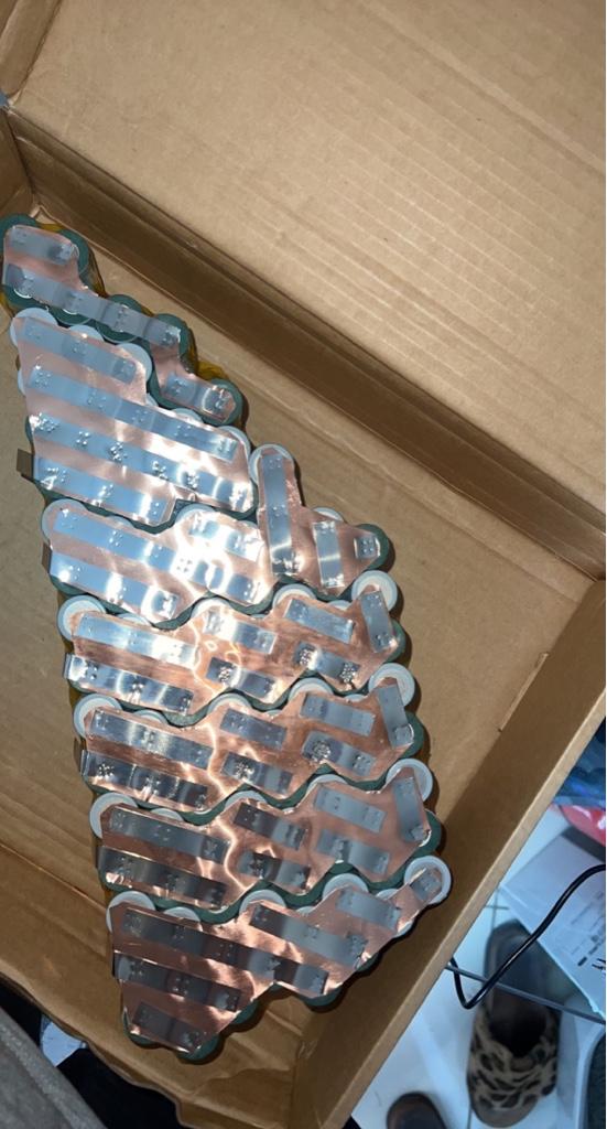
Sometimes the problem is faulty interconnects--some cells in a group are no longer connected to the others, so they no longer contribute to the pack in any way other than taking up space and making it heavier.

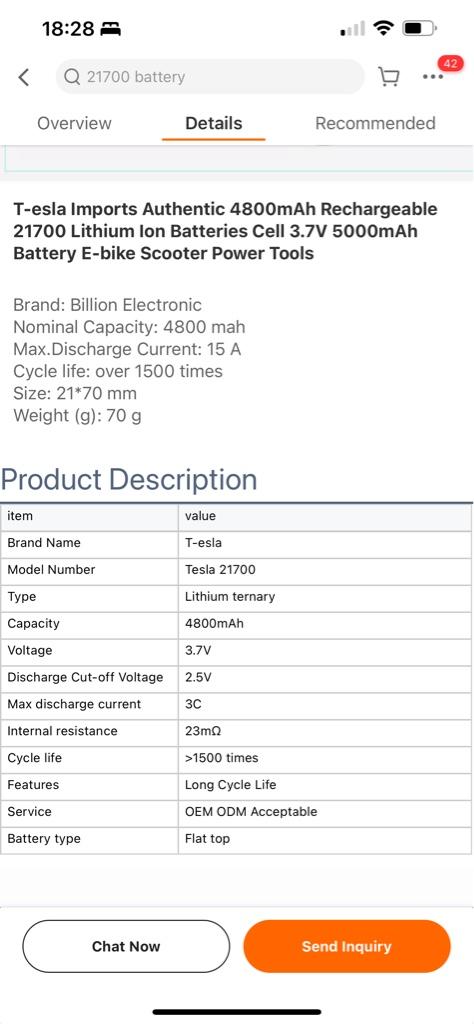
Sometimes it's that the cells are not even from the same batch, and weren't tested for matching properties before assembling into the pack.

Sometimes it's that the cells are actually recycled garbage cells, from scrapped packs, or defective batches, etc., that should have been recycled but were instead sold as new cells, or just collected by a pack manufacturer, etc., and

Sometimes it's a defective BMS, with a stuck-on resistive/shunt balancer. Even with a low (50mA or less) current, since it's draining that *all the time*, continuously, from that cell group, whether charging, discharging, or just letting it sit there, it can cause a severe imbalance that will grow worse with time: every hour a 50mA balancer drains 50mAh. In 10 hours that's 500mAh (half an Ah). In 100 hours (a few days) that's 5Ah. Etc.

DefconExile said:
I’ll have a little ride around the woods take it back and test the groups again and see if it’s possible that one group isn’t draining.

If you mean that one group isn't draining (discharging) while riding...that can't happen because they are in series. All seriesed groups (cells) discharge at the same current, same "rate".

They end up at different states of charge afterward because they have differing capabilities and capacities.

The only way to have a pack that stays at the same SoC for all groups during the entire charge and discharge cycle is to have groups that are all equal identical capabilities and capacities.

All balancing (top or bottom) does is make all cells the same *voltage*; it cannot make them the same capacity; that's intrinsic to the individual cells.
 

If you mean that one group isn't draining (discharging) while riding...that can't happen because they are in series. All seriesed groups (cells) discharge at the same current, same "rate".

They end up at different states of charge afterward because they have differing capabilities and capacities.

The only way to have a pack that stays at the same SoC for all groups during the entire charge and discharge cycle is to have groups that are all equal identical capabilities and capacities.

All balancing (top or bottom) does is make all cells the same *voltage*; it cannot make them the same capacity; that's intrinsic to the individual cells.[/quote]

Thanks for clearing up a few things for me. If they all drain regardless could it be a case of like you said making sure all groups have equal capability , could one of the cell groups ( most likely group 11) have a bad connection in parallel causing it to become charged quicker than the rest and at the same time discharging quicker or worse a bad cell altogether

I imagine ideally I should have tested the capacity of each cell beforehand to cancel out this possibility. This is my first ever build so everything is a learning curve

Also I’m not sure if this could be the issue. If you see on the photos where I’ve used the copper-nickel sandwich method to do both parallel and series connections on some connections the copper is larger than others , could this create more resistance in certain areas causing the groups with less resistance to drain faster and also charge different groups at different rates , I could be waffling but it’s just a thought
 
Some interesting results after a 5 minute ride full throttle , here’s the voltages

1-3.93v
2-7.77 , 3.84v
3-11.6 , 3.83v
4-15.43 3.83v
5-19.28 3.85v
6-23.1 3.82v
7-26.9 3.8v
8-30.8 3.9v
9-34.6 3.8v
10-38.4 3.8v
11-42.5 4.1v
12-46.5 4v
13-50.3 3.8v

It appears the majority of the pack is relatively balanced whereas groups 12,11,8 and 1 are sitting slightly higher than the rest , I’m going to remove the fish paper and insulation to take a better look at the spot welds , group 11 is the most problematic so I’ll focus my attention there.

Before painstakingly dismantling I’ll attempt to charge it so I can clearly see the balance light on the BMS and weather it’s actually activating. I have seen the balance light come on before but not for long maybe a second at most and then the charger shuts off along with the balance light as it hits HVC

What are thoughts on a completely separate active balancer that’s constantly balancing the cells as opposed to just when it’s charging and hits 4.18v . This seems more ideal and originally is what I thought the BMS took care of


Sent from my iPhone using Tapatalk
 
Ok so the balance light came on for 5 minutes or so and then began repeating as before , charger shuts off and so does balance light , then turns back on again along with the light , off and on repeatedly in progressively slower and slower segments


Sent from my iPhone using Tapatalk
 
DefconExile said:
Hopefully it’s a case of being badly balanced from the get go...
DefconExile said:
I should also mention all 104 cell in the pack were charged to 3.65v or 3.66v before spot welding
:? Not sure which side you're leaning towards but it looks like you did do a good job balancing the cell voltages before assembling-- the slight difference between 3.65v to 3.66v should be close enough, no?
 
DefconExile said:
1-3.93v
2-7.77 , 3.84v
3-11.6 , 3.83v
4-15.43 3.83v
5-19.28 3.85v
6-23.1 3.82v
7-26.9 3.8v
8-30.8 3.9v
9-34.6 3.8v
10-38.4 3.8v
11-42.5 4.1v
12-46.5 4v
13-50.3 3.8v
If you know the specific model of cell, you can look up it's state of charge vs voltage curve, and see the capacity difference between groups based on your voltage readings. Some thoughts / analogies on this below.

DefconExile said:
I should also mention all 104 cell in the pack were charged to 3.65v or 3.66v before spot welding
This from a previous post indicates the cells started out equal in voltage the middle of their capacity range. But it doesn't tell you anything about their relative capacities, resistances, or other capabilities, which can still all be unequal.

If you have 13 cell groups all charged to 3.65v before interconnections are made, but say, 9 cell groups are the same capacity as each other, but 4 are not, then the 9 will stay in relatively balanced voltages throughout the charge and discharge cycle (entire SoC curve), while the other 4 will vary, as they are filling and emptying more quickly or more slowly than the other 9.

A very inexact analogy is like having 13 glasses for water, but some of them are smaller than others and some are larger, but all you can see is the level of the water (voltage)--you can't see the actual size (capacity, Ah) of each glass.. The pipe to fill them all is exactly the same size (current, A), to emulate them being in series. The smaller ones will become full faster than the "standard" sized ones, so they will seem to hold more than they actually can, and the larger ones won't fill as quickly and seem to hold less, etc.


It appears the majority of the pack is relatively balanced whereas groups 12,11,8 and 1 are sitting slightly higher than the rest , I’m going to remove the fish paper and insulation to take a better look at the spot welds , group 11 is the most problematic so I’ll focus my attention there.
I'd guess that a connection problem from a weld issue wont' be directly visible, though any welds that are significantly different in appearance from others could indicate a welding problem--for that you should check the weld threads to see pics of good vs bad welds for the specific type of welding your pack is built with, if there are any. The interconnects themselves block access to the cell end caps so you can't do a continuity or voltage difference test between the interconnect and the cell itself.


Before painstakingly dismantling I’ll attempt to charge it so I can clearly see the balance light on the BMS and weather it’s actually activating. I have seen the balance light come on before but not for long maybe a second at most and then the charger shuts off along with the balance light as it hits HVC
That rapid a cycling usually means that even a small momentary current is raising the voltage of the cell group above HVC, and that usually means that cell group is a lot higher resistance than the others that aren't doing that. That can be from disconnected cells in a group, or problematic cells in a group.


What are thoughts on a completely separate active balancer that’s constantly balancing the cells as opposed to just when it’s charging and hits 4.18v . This seems more ideal and originally is what I thought the BMS took care of
I noted some thoughts about active balancers in a previous post--but remember that all any balancer does is make the cells all the same voltage.

They dont' fix the problem that causes the imbalance, they just keep the imbalance itself from getting so bad over time that the pack can't be used at all.


DefconExile said:
Thanks for clearing up a few things for me. If they all drain regardless could it be a case of like you said making sure all groups have equal capability , could one of the cell groups ( most likely group 11) have a bad connection in parallel causing it to become charged quicker than the rest and at the same time discharging quicker or worse a bad cell altogether
Yes, those are some of the several possible causes.

Except that no cell (group) can charge or discharge any faster than the others in series with it, because the current thru them is all the same. Their voltage drops or raises more quickly, making them appear fuller or emptier more quickly, but they aren't truly filling or emptying at a different rate, if that makes any sense.

They can charge to a higher voltage or discharge to a lower one more quickly because they have less capacity, but they aren't actually charging or discharging at a different rate (faster or slower).


I imagine ideally I should have tested the capacity of each cell beforehand to cancel out this possibility.
That's the next most ideal case to using brand new well-matched cells (that won't ever be pushed to their limits, and not charged full or discharged to empty, which is how large-EVs keep their packs healthy).


Also I’m not sure if this could be the issue. If you see on the photos where I’ve used the copper-nickel sandwich method to do both parallel and series connections on some connections the copper is larger than others , could this create more resistance in certain areas causing the groups with less resistance to drain faster and also charge different groups at different rates , I could be waffling but it’s just a thought
Again, you can't charge or discharge them at different rates, because they're in series. ;)

The resistance of the parallel connections within a group would have to be very very high, effectively open-circuit, to prevent cells in that group from equalizing with each other over time. If the resistance is high enough (still very high), however, it could certainly affect current flow between cells during charge and discharge enough to cause voltage sag or rise on those groups, affecting the way the BMS reacts and controls the charge or discharge ports.

Resistance of series connections being high would limit the current flow of the entire pack to what could flow thru the worst-case connection, and cause voltage drop under load over the entire pack output; you'd notice this during a ride if you have a voltage display, anytime a load was applied you'd see excessive voltage drop. (you will also see that for group-level problems, too, so it's not a way to differentiate between them; you'd have to measure voltage across each interconnect from one group to the next, under load, to see if the interconnects are high enough resistance to cause a drop--if they are good, you'll see virtually zero voltage from one cell group's positive to the next more positive one's negative).
 
Back
Top