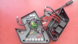
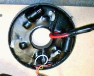
First E bike A2B need help.

Ok making progress, when I take the Battery's output & switch it from input “A” to Input “B” on the switch module as suggested I can deffnatley hear a relay Click on & Off with the Key. Switching battery's output back to input “A” reviles I have no relay click on or off. What next?
Thank you so much for your help so far.
 
And I tryed testing the rear hub by hooking the battery directly to the Rear hub and Nothing?
Don’t know if disconnecting battey from the switch module and plugging into the wheel is a good test cause do-sent the hub motor need the switch module to operate the throttle?

What do you guys think. Does it sound like the Hub motor/ controller is bad?

We know The A side of the switch module is not working because we don’t hear one of the relays clicking on. But B seems to work, and I have 37 volts at the rear hub? What do u guys think is left?
 
Kinda sounds like the "A" battery switching circuit is damaged. Swap it back to "B" and turn the key, with everything reconnected, you should see the 3 LED's on the throttle light up.

If you do see the S.O.C. LED's, leave the key on, unplug the smaller 4 pin plug going to the motor.

Be very careful not to let the probe tips of your multi-meter bridge any 2 of these pins together. Be precise.

You should see somewhere around 6v on one pin (it should go back to 0v with key off), a ground on another pin, the throttle signal (1-4.3v) on another pin, and the last pin should have your brake signal.
 
With the battery plugged in to the B side of the switch module and the relay clicked on I have no SOC indication lights on the grip.
 
But you are getting a key on, key off, 36v on the 2 pin motor plug?

If this is the case, trace the SOC / LED wiring from the throttle to where it plugs in. Check for voltage on the other side of that plug. Maybe the connection is bad/corroded.

Edit: If I'm not mistaken, the Relay module takes the 36v, uses a buck converter to drop the 36v down to 5-6v to supply the throttle and the internal controller with 5v for their respective hall sensors.

The relay box should also have a fuse. Did you check that?
 
The Key is giving me power to the hub in Both configurations. Example
Battery plugged into switch module in the stock configuration A to A = No relay clicking on but 37 volts at rear hub no SOC lights
And
Battery plugged into switch module B port Key switched to B, relay clicks ON 37 volts at rear hub
No SOC lights

The 40 amp fuse in the switch module is good. I pulled it and check it for continuity.

I have not checked any of the pins from the hub motor. I take it I would be checking the Male pins coming from the hub motor? OR the Female plugs comming from the switch module
 
Gwest said:
The Key is giving me power to the hub in Both configurations. Example
Battery plugged into switch module in the stock configuration A to A = No relay clicking on but 37 volts at rear hub no SOC lights
And
Battery plugged into switch module B port Key switched to B, relay clicks ON 37 volts at rear hub
No SOC lights

The 40 amp fuse in the switch module is good. I pulled it and check it for continuity.

I have not checked any of the pins from the hub motor. I take it I would be checking the Male pins coming from the hub motor? OR the Female plugs coming from the switch module

This sounds like the "A" relay has fused contacts, leaving it always on regardless of the control coil being energized. A continuity check with the "A" battery plug into the relay module and the 2 pin out to motor should confirm this.

The SOC lights should be coming from the relay module. I don't think there is any circuitry that goes from the controller back to the SOC.

I'm not 100% sure on this one. Not sure if the relay module or the motor controller produces the 5v signal for the throttle. Maybe fetcher can help on this. My assumption is the motor controller, so I'd check the motor side of the 4 pin.

My old A2B had no real issues. I just swapped the controller out for a 72v 45A external one and installed my own halls into the old motor. Still only did 20-21mph but was much more peppy.
 
As far as I know, the throttle voltage comes from the internal controller and just passes through the switch module.

Swapping the battery to the B input indicates the A relay coil is open. If the contacts were welded, you'd have power to the motor.

If you use the B battery input and get power to the motor, you should be able to measure the 5v (or 6.25v) on the throttle.
There should also be voltage on the SOC meter wires.

If the ground wire for the throttle is broken, this could cause both the throttle and SOC meter to not work. It should be connected to battery negative.
 
So you think it may be the Throttle?
How do I test the Throttle Neg.
 
So I took my MM and tested the 4 Pin connector as suggested above. I tested the side comming from the switch module under the BB.

With the Key ON. And 37 volts going to the Hub,
I got nothing from all 4 pins, no voltage from any of the pins.
 
I'll stick the wiring diagram in here again:

A2B Metro wiring diagram.JPG

Well, progress at least. Power to the motor is half the battle. The 4 wire cable coming from the motor should have voltage on the red wire. You might try disconnecting it at the motor and try measuring on the pins coming from the motor. Put your meter negative to the battery negative. Be really careful not to short the pins. It could possibly make the motor run. Look for the 6.25v.
At the motor connector, you might be able to make it run by connecting the 6.25v line to the EAI (throttle signal).

If you have 37v going into the motor and nothing on any of the 4 pin wires, then the internal controller is bad or the wires broke. They get broken easy right where it comes out of the axle. Visually inspect that area.
 
Ok Thank u for the info and the Wire Diagram. I will perform that test right now. And report back.
 
Ok if your looking at the Round 4 pin connector like a clock. Going clock wise (left to right) with key On and power coming from the battery and 37volts, My MM is grounded to battery’s black ground. I have these readings, (these readings are comming FROM) the hub motor female side of the 4 pin connector

Pin #1 0.045 and go’s to 0.000 with key off.
Pin #2 0.000
Pin #3 0.000
Pin #4 0.000

No voltage @ all comming from the same “male side” of all 4 pins of the 4 pin connector
 
Time to get inside the hub and check for damage.
That's Something I wanted to avoid.

I found a guy selling complete Ultra Motor rear wheels, Un fortunately these are the Newer Hub Motors with the Controller Located
out of the hub. What would be involved in Up grading to this new wheel and external controller
 
Where are you located? I have one sitting in the garage.

Taking apart the motor is no fun, even with the right tools. Since I've done it a couple of times, I'm not daunted, but it is time consuming to rebuild the spokes afterward.
 
I’m in redwodcity Ca Nor Cal
 
Yes, unfortunately sounds like a possible direct short-circuit in the controller/motor is what caused the 'A' relay contacts to fuse together in the first place?

Go the replacement orig rear wheel assy if poss! ;)
 
Thanks Do you have a recommendation for sourcing a new rear wheel
 
No worries.. then it's only a wheel swap you'd need to do.
~ Sounds like 'fechter' may have a wheel in his garage? Or is it a non-in-hub-controller model?

'New' is less likely than 2nd hand, obviously ~ but I'll certainly keep my eyes & ears open for you anyway.

In the meantime, you may now have little to lose by opening up your existing hub and checking for short circuits/burned out components etc?
If the actual motor looks good still, you could always modify and fit an external generic controller.. at least that way you will also have circumvented the potential in-hub controller over-heat/cut-out glitch and also achieve smoother quieter running on the UltraMotor?

;)
 
Hey Guys hope everyone had a great Memorial Day weekend. Ok so I wanted to try and get this back on track. I have not been able to make any more progress.

Sounds like we are not sure weather it's the switch module or the rear wheel or BOTH.

I found a guy selling a Brand New ultra motor rear wheel. BUT it’s the kind with the controller located in the frame.

What would be involved in getting a ultra motors frame mounted controller retro fitted into what I have?

I would be up for what ever Parts I could get from members here to get the bike fixed
 
Switch Module sounds 'OK' - apart from it's fused 'A' relay contacts

So problem could be either in motor or controller.. which is perhaps a fair reason to attempt to strip it down and check it out anyway?

Personally I have never come into close contact with the Gen 2 in-frame controller model and don't know whether the BMS/wiring also changed at that point?

The Gen 2 controller looks to have an upgraded switch module too.. both built snuggly into the frame end cap and reducing the old 'rats nest' entanglement a little!

If your existing motor is OK and/or you replace the wheel with a Gen 2 model, perhaps another solution worth considering, is to fit a modern generic external controller in either case anyway? ~ Bit of a wiring 'headache', but an excellent long term investment both reliability & performance-wise, I reckon! ;)

Otherwise, yes - this site is certainly a good place to be for advice AND spare parts! ;)

Pix of Gen 1 & Gen 2 controllers:

Gen 2 contoller & Switch Module.JPGIn hub controller.jpg

Hope this helps a bit. :)
 
Gwest said:
I would be up for what ever Parts I could get from members here to get the bike fixed

I have a first gen original motor I can part with. Problem is..... it has already been converted to run with an external controller.

It has Honeywell halls installed and the controller was removed. I used a High Flex 10 Conductor (3x12g + 7x24g) Motor Cable from Grin Technologies. It has a syringe of Statorade in it as well.

Option 1> You could buy any 36v controller and this would get you going provided you don't feel comfortable opening your motor and converting it (if it's just the controller that's bad). You could take this known good motor and your broken one to a bike shop and have them swap wheels, lace and true it. My wiring is color coded to match the very common "KT" controller, so that part should be really easy. Mount the controller on top of or below the rack under the seat, run the cables down to the swing arm and make your connections, I think I put some 45a Andersons for phase and some JST's for the halls.

Option 2> I also have the original in wheel motor controller. This is if you're good to go with a 3 jaw puller, a vise, a soldering iron and the smarts to keep all your fingers after separating or putting the motor halves together. (Or I could do it.... for a wee bit more $$$)

To do it, the halls will need to be re soldered to the board once the controller is properly aligned and bolted down inside the wheel. The halls are epoxied in so this would be the most difficult part. The cables would need to be retro fitted as well. Then spoked, re-laced and trued. I don't think I have the original wiring so you'd or I would have to get some replacement cables and retrofit both sides. Truly a pain in the ass. I have the parts you need just all in seperate pieces.

It's a lot of tedious work to go back to factory but it is do-able. I'd also throw in the last of all my good A2B parts; a BMS, a switch module, 2 extra bearings and anything else A2B I have stored.

PM if interested. Not looking to make money here, just cover the shipping and a tasty craft brew or two. I'll try to post some pics tomorrow. Maybe someone else following this needs something you don't.
 
Back
Top