Fried controller revival - Simple fix?

bobb513

1 µW
Joined
Feb 11, 2021
Messages
4
Good day, first time posting. I have an FX-15 fat tire bike from BPM Imports, and it is my only mode of transport to and from work.

It runs on a 48v 13AH battery. Ito was using the bike in snow, and probably overloaded the controller with stall load. I believe the unit is recoverable with some input from those more familiar because of the way it blew. I turned on the bike, went in for gloves and helmet, and came out to find it powered off.

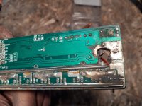
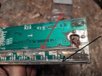
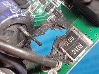
First thought was that it timed out, but no such luck. No power on to be had. I brought the bike back in the garage, and tinkered with the controller wires. Bad move, as I moved the POS battery wire it let out a shorting sound. I immediately removed the battery. I proceeded to open up the controller and found the POS battery wire was completely disconnected. I blew a hole right thru the PCB. I suspect that no components failed, but the solder joints became overheated, leading to an open circuit. The short only happened when I moved the wire.

My question is

'how is this wire intended to be tied in?'

You can see the capacitor prong,(actually both prongs.) note also that the NEG battery wire has also become unsoldered.

As for the crater left in the board, I was considering a slice of a MIG welder contact tip to slide over the cap prong, then fill - but without bridging across any wrong contacts.

I will be ordering a replacement controller, probably upgrading to a 35 A 1000 watt box, and perhaps an LCD8H. But right now I just need a quick fix.

Seems like a simple fix once connection is confirmed. TIA, Bob
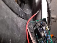
20210210_184319.jpg

20210210_185923.jpg
 
That kind of failure is not really a simple connection failure. :( It could be, but I've seen this kind of thing before (though not usually with a hole in the board ;)

The thing is, in order to get that kind of arcing to cause such damage, you have to have very high current, like a direct short from battery positive to negative. That *could* happen if hte red wire had come out and touched the black wire or negative pad, but there isn't enough left of the area to tell if that's what did happen.

From previous experience, the most likely thing is that FETs blew up...which can be a "silent" failure where they just become shorted. When both top and bottom banks of FETs in a phase short, it directly shorts the battery input, and that kind of current can be so high that the board traces can literally evaporate into plasma, and plasma is VERY HOT (arc welding, or lightning, for instance). The plasma allows arcing to continue even thru a hole, and that then burns and evaporates all the solid substance around it until it finally reaches a distance that arcing can't continue, or something else fails (fuse, BMS, wires, etc), or it all just catches fire.

So, it's very likely that you have several problems.

Blown FETs, which may have taken out all their gate drivers too (common).

High-energy RF from the arcing may have damaged other electronics in the controller, and/or anything else connected to the circuit it occured on.

That potentially includes (though not all that likely) even the BMS of the battery (the short itself may have also done this, if the battery has no fuse--sometimes the battery BMS FETs *also* fail shorted, so it can't turn itself off to protect the pack anymore).


So the first test I'd recommend is, with the controller disconnected from the system entirely (including the motor), to use a voltmeter on continuity or the 2ohm setting, to measure from battery positive (red meter lead) to battery negative (black meter lead). It should read OL or whatever indicates an open circuit, because most of the paths it could take are now vaporized.

Next, measure from one of the main long "busses" that all of the FETs connect to, to the other one. S33e pic below, where red lead and black lead connect (I think I have the colors swapped). That should also read open circuit, though it might take a few seconds to reach it because it has to charge the capacitors first. If it doesn't, then you have a short circuit in the FETs themselves, and at that point it's a lot of work and money to replace a bunch of parts on there, and other things may be destroyed that you won't know until then...which will then cost more time and money to replace. IF the gate drivers are blown in a way that turns on both sets of FETs in a phase, then it will blow them up again, so then you have to replace all those FETs *again*, too.
20210210_185923.jpg

Myself, as much as I like to save and fix things (take a look at my build threads :lol: ) would write this controller off, and buy a new one....


The battery...you'll also need to test that. With it unplugged from the bike, use your voltmeter on 200VDC to check the main connector that would plug into the bike. If you get the normal voltage from it, it's probably ok--you'd want to put a load on it (heater coil, 100w+ incandescent light bulb, etc) to make sure it's working under at least a small load. But to find out if the FETs are shorted on, you'd have to put it into a condition that should turn the output off, and see if it actually does so. Usually the two things that do that are LVC, probably around 42v for your pack, maybe as low as 38-39v, or overcurrent, which I don't know what that is, if it even has one (if it did, that should have been triggered by the problem that caused the controller damage, which would have stopped the arcing on it's own).
 
Toast. I think if you need a quick fix, order a replacement off of Amazon with 1 or 2 day shipping.

What are your battery specs? "Upgrading" the controller may equate to killing your battery, so make sure your battery can supply 35A continuous. Looking at the bike online, it looks like it's spec'd at 750W, so the battery probably can supply around 16A to 20A if made with generic Chinese cells.

My guess is that the current pack uses generic cells, since: 1. they don't mention the cell type in the specs for the stock battery, and 2. they sell the same form factor replacement battery, with Samsung cells, with a 21Ah capacity. If they are 35E, that would be a 13S6P pack and might be enough for your upgraded controller.
 
HI Amerwolf, thx for the quick response. I will do the test to check the battery BMS. That does have me concerned, and I never gave it a thought. I do think back to watching a guy short out his 48v taillight pretty intensely (installed with no fuse.) He was able to ride away. Thought for sure that battery was going to blow. So I do have a ray of hope. Worse case, a $500 battery is surely worth replacing the BMS.

But due to the atypical way this controller blew, I don't know that FET's or gate drivers were 'in circuit' so to speak, meaning they were not within the range of the short. Anything that lay between the short seems more at risk. While there was enough (stall surge) heat to loosen the solder joint on the POS battery wire, the FET's held up fine to the stall amperage surge from the snow riding. The bike rode for a week after the stall surges, and was not being rode when it failed from an open circuit occurring from the low amp draw of only the power on. That low draw is likely what opened the faulty circuit. Had I used the bike right away, the higher draw probably would have fused the wire on.

My guess is this loose wire would not have happened if the manufacturer had used a solder with a higher melting temperature.

Having said this, I've cleaned the board more to look for other damage, and found a wayward trace, and a resistor that took some peripheral heat from the arc. The trace appears to have originated from the POS pad, as you can still see it's eyelet. That resistor (labeled "115") needs to tie into something as well.

I'll be sending a contribution, thx

20210211_235330.jpg

You have confirmed my suspicion that the POS wire need to tie into the POS rail, as does the POS cap leg, and the said trace.

Salvaging this unit is more about time than money. I see that Amazon has some next-day 22A max/500W units (proly 6 FET) available as a temporary fix (the original was 25A, 750W/9 FET) Seems like the better units are all west coast, and I'm in NYC.
 
Hi E-HP,

Thx for the input. I did confirm before buying that the 13 AH battery does in fact use Samsung 35E. It will be a bit of a project to upgrade BC the original controller uses those SM connectors, which are not waterproof. The better controllers use those rounded watertight connectors. I'll need to buy an external enclosure as the upgrade won't fit inside. Perhaps they make an extension cord for the Bafang motor wire, which does of course have the 9 pin waterproof plug. Full sine wave will consume more power, but increase torque. Thumb throttle won't work with many of the better controllers either, demanding twist (I thought a pot was a pot.) Have yet to find a brake light wire in the offerings for my specs. Bot a DC-DC converter, as well as a 48v light, but thus far I'm still running a $15 battery light with cable mounted brake light switch.

Regards, Bob
 
bobb513 said:
But due to the atypical way this controller blew, I don't know that FET's or gate drivers were 'in circuit' so to speak, meaning they were not within the range of the short.
"range" of RF energy from an arc big enough to do that is up to several meters or more--it's a LOT of RF energy. If you're curious, setup an old AM radio near an arc welder....see how far away you can go and not hear bursts of static from it, on every band. ;)

HEat damage from the arc is pretty severe close in, and if it goes on long enough is severe within several inches of the arc if it's a big enough arc...but it does fall off fast, if you've ever done any welding you probably know how this works. If you haven't...try it out and then imagine that process going on inside your controller.... :shock:

My guess is that is why there isn't any solder on the negative battery wire--it was heated to evaporation by the arcing, and before that it was perfectly fine.

However, it's not that I think the fets would be killed by the arc (though they could be), it's taht the fets being blown (shorted, which is how they usually fail) would *cause* the arc thru first vaporizing ing the PCB traces from severe overcurrent allowing a gap and then arcing across the gap.

It is *possible* a poor connection / cold solder at a main power wire could arc under high load, and result in something like you see, but it would also vaporize the entire end of the wire with the poor connection, so either the positive or negative battery wires. And it would *only* happen under a high current load.

If you were not riding hard at the time, then the only other way a high current load could occur is if the controller was shorted inside, and that could only happen if either the FETs are shorted on at least one phase from bat+ to bat-, or if the battery wire had actually come completely out of the board's hole and shorted to the other battery wire (or a pad or trace leading directly to that wire).


While there was enough (stall surge) heat to loosen the solder joint on the POS battery wire,
It takes several hundred degrees to melt solder. If it got that hot on that heavy duty a current path, other parts in there (Fets, caps, resistors, circuit board) would have gotten even hotter and the whole thing would've gone up in smoke. ;) YOu would never ever see this kind of heat in simply operating the bike--not with the low-power controller, battery, and motor that are on there.

The solder connections in there aren't ever going to get hot enough to melt the solder without some other failure happening first to create the heat--current flow thru them aint' gonna do it. (unless it's so much current flow that it's destroying everyting else in the same path, like FETs, shunts, etc., and thsoe would all go before that one does, and it would also melt all the insulation on the wires in the path from the battery to the controller, both positive and negative, because they're the same path).


That low draw is likely what opened the faulty circuit. Had I used the bike right away, the higher draw probably would have fused the wire on.
low current doesnt' open circuits like that.

To have high enough current draw to remelt the solder would, as noted above, destroy the wires and the rest of the controller first (and the battery's BMS at the least, and probably the cells; most likely it would be a very pretty fire).


My guess is this loose wire would not have happened if the manufacturer had used a solder with a higher melting temperature.
No, again...other stuff would fail way before the solder melted.

The most likely cause for loose wires, if they were already loose before the failure, is simple bad soldering, called "cold solder joints", which usually happens when a wire is moved before the solder cools, or is never heated sufficiently in the first place to fully melt the solder and wick it into all the places it needs to go, and not using sufficient solder in the process. The larger a connection is, the more heat it wicks away and the faster it does so, so the harder it is to solder it well. It's a common enough problem with inexperienced builders, and I expect there are a fair number of those in factories at any point in time, before they do it enough times to get it right (and their learning process is likely all "live", meaning on units that will all go out to customers with no QC on them, based on the various and copious failures I've seen over the years ;) ).

Having said this, I've cleaned the board more to look for other damage, and found a wayward trace, and a resistor that took some peripheral heat from the arc. The trace appears to have originated from the POS pad, as you can still see it's eyelet. That resistor (labeled "115") needs to tie into something as well.
I don't know where each thing would have tied in. The most likely is that it would connect to the stuff closest to it that it is "pointed" at. But connecting it to the wrong things could destroy whatever isn't already destroyed in there.

And if there *is* a short in the controller (FETs, usually), and the battery isnt' damaged yet, you could damage it by reconnecting it to this controller again in it's "repaired" state.

Then you have a battery to fix as well as a controller, and are down for even longer. :(
 
bobb513 said:
It will be a bit of a project to upgrade BC the original controller uses those SM connectors, which are not waterproof. The better controllers use those rounded watertight connectors.
You can replace the connectors on either the throttle and other stuff or on the new controller, so that they match each other. I would recommend keeping any new waterproof connectors on whateve they come on, and changing out the non-waterproof ones to those. Usually they are Higo, and several places around the web carry pigtails you can solder in; some are long enough to do this inside the device housings, and some are short so you would need to do inline splicing.


Full sine wave will consume more power, but increase torque.
N....where does this information come from? :?

Thumb throttle won't work with many of the better controllers either, demanding twist (I thought a pot was a pot.)
Actually, none of them are pots. They are all hall sensor based. ;) (you can *get* pot throttles, like Magura, but they are quite uncommon--the cheap hall throttles are almost everything out there).

It does not matter what physical format the hand control is in, the device inside is the same, and would connect the same--5v power, ground, and a signal wire. Any other devices included in the control have other wiring, which varies. Different versions of throttles have different motion ranges vs output ranges, and different actual voltage ranges by a tiny amount, and different offsets in the motion vs output ranges, etc., but they will in general all work with all typical ebike controllers. It would be very unusual to run across one that doesnt' (and even more unusual to find one that would work with an unmodified (by the user!) pot throttle).


Have yet to find a brake light wire in the offerings for my specs.
Could you explain in complete detail what a "brake light wire" is, and what your specs are, and what "the offerings" are?
 
bobb513 said:
You have confirmed my suspicion that the POS wire need to tie into the POS rail, as does the POS cap leg, and the said trace.
FWIW, the resistor and transistor just beside the burned hole probably *used to be* the input stage for the battery-current-monitoring. I don't know the exact circuit, but the resistor probably used to go to the FET side of those shunt resistors.

However, there may have been other actual components in that circuit taht don't exist anymore, along with all the traces that connected them together. It is possible that directly connecting that resistor to the negative battery (via the shunts) could damage something else in the controller (although it is unlikely).


I don't have any links to specific threads, but there are some around with bits of partial user-created schematics for various old controllers, mostly in threads from about 5-10 years ago about modifying "infineon" controllers for "high power" or "overclocking" (same thing, rather than what it means in a computer). They might be enough to help you rewire across the hole more safely...but keep in mind that none of them will be the same brand/model as yours, and so could ahve significant circuit variation from it.
 
bobb513 said:
Hi E-HP,

Thx for the input. I did confirm before buying that the 13 AH battery does in fact use Samsung 35E.

Sort of doesn't make sense. If it were a 3P battery, that would be 10.5Ah battery. If it were a 4P battery, that would be 14Ah. Most manufacturers would call 4P of 35E battery, 14Ah battery not 13Ah. 4P would be 32A continuous when the cells are new and degrade from there.
 
E-HP and Amberwolf. All input acknowledged, respected and appreciated. Covering a few other bases, but will follow up soon
 
Back
Top