Giant Lafree middrive motor possible replacement

By putting a 15amp switch on the negative pole of the motor, I was able to run the motor and check the wattage of the motor with no load.

It measured about 76 watts.

So, it seems like there's a bad throttle or controller, right? The controller was rated for 500 watts.


IMG_20230122_110247908.jpg
 
Can you link to the specific page you bought the controller from? it may have info needed to troubleshoot.

Which kind of throttle do you have? And exactly how is it wired to the controller? (if you can show a picture of the controller with every wire labelled to where it is actually wired to, it may help). (even if it came with the controller, there's no guarantee it's the right kind and/or wired correctly, though it increases the likelihood that it is)

Some brushed controllers require a potentiometer, or resistive throttle, not just because of voltage range but becuase of the input circuit (may use the resistive path as protection).

A hall throttle works differently and has a different voltage range. Controllers that require a potentiometer may not work with a hall throttle because the hall starts at a higher than zero voltage, so the contorller can go into protection mode and not operate because throttle is "on" when the system is powered on.

Also, a hall throttle requires specific wiring to make them work and/or not damage them, while a pot throttle can be miswired in certain ways and still work (though they would operate backwards, and again could put the controlelr into protection mode).
 
amberwolf said:
Can you link to the specific page you bought the controller from? it may have info needed to troubleshoot.

Which kind of throttle do you have? And exactly how is it wired to the controller? (if you can show a picture of the controller with every wire labelled to where it is actually wired to, it may help). (even if it came with the controller, there's no guarantee it's the right kind and/or wired correctly, though it increases the likelihood that it is)

Some brushed controllers require a potentiometer, or resistive throttle, not just because of voltage range but becuase of the input circuit (may use the resistive path as protection).

A hall throttle works differently and has a different voltage range. Controllers that require a potentiometer may not work with a hall throttle because the hall starts at a higher than zero voltage, so the contorller can go into protection mode and not operate because throttle is "on" when the system is powered on.

Also, a hall throttle requires specific wiring to make them work and/or not damage them, while a pot throttle can be miswired in certain ways and still work (though they would operate backwards, and again could put the controlelr into protection mode).

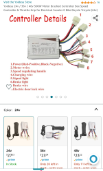
Here's the link Yoidesu 24v / 36v / 48v 500W... https://www.amazon.com/dp/B07WFRXPJH?ref=ppx_pop_mob_ap_share

I wired the new throttle And tried the OEM throttle. Curiously, the old one, when tried, caused the motor to turn something internally and drew 7watts, but didn't turn the sprocket.

The power lock is jumped. I had the connections soldered or crimped so contact seemed good. Not a great picture of the connections. The yellow blue pair to the motor is a question. I have yellow from controller to pos motor, blue to ground.

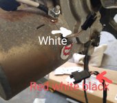
Curiously, there are a pair of white wires on the motor and I tried jumping them. Also there's a red, white and black set that I tried putting the throttle in series with the throttle.

IMG_20230122_140255420~2.jpgIMG_20230122_140428915~2.jpgScreenshot_20230122-135610-048.png
 
Zephak said:
The whole link doesn't open, but this part does
https://www.amazon.com/dp/B07WFRXPJH
and provides this image for connections:
https://m.media-amazon.com/images/I/61UchC+ZPDL._AC_SL1500_.jpg
61UchC+ZPDL._AC_SL1500_[1].jpg
On that, the throttle wires look like typical colors that often (but don't always) mean
black-ground
blue-signal
red-5v
You can measure on the controller itself with no throttle connected, just battery, to see which is which, using battery negative for your meter black lead, meter on 20VDC. You'll get 0v for ground, about 5v for 5v line, and anything at or above 0v for signal.


The included throttle picture looks just like a couple of hall throtles I've worked with. Most of the pot throttles have a different, often larger, part next to the grip where it mounts to the bars (to fit the pot and sometimes gearing to turn it from the grip). (you can look up Magura or Domino for a couple of well-known pot throttle types, if curious).

Additionally, it says 1v-4v on the controller, which is for the throttle signal range, and that is for a hall throttle (a pot throttle can work but will have some deadzones at top and bottom of range where it doesn't do anything or doesn't change the motor speed).

Curiously, the old one, when tried, caused the motor to turn something internally and drew 7watts, but didn't turn the sprocket.
That probably means there is a freewheel or clutch inside the motor so it only turns the sprocket in one direction. Swap the motor wires and it should then run the sprocket.

But it does mean that most likely all other wires are correctly connected.

The yellow blue pair to the motor is a question. I have yellow from controller to pos motor, blue to ground.
The order determines motor spin direction.

Curiously, there are a pair of white wires on the motor and I tried jumping them. Also there's a red, white and black set that I tried putting the throttle in series with the throttle.
White wires on the motor could be a temperature sensor or thermal breaker. What does a multimeter read on them when set to 200kohms? Does it change as the motor changes temperature?
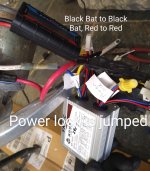
 
@Amberwolf the explanation of the throttle wiring led to the answer: the throttle that was shipped with the controller had the connectors in the incorrect places.

The connection was supposed to be plug and play, which is what I wanted to eliminate mis-wiring it. But the black ground on the throttle was on the outboard side.

The white wires on the motor are normally closed and I am going to ignore them, I think.

The motor needs the blue/yellow wires reversed, but I think I am on my way!
 
Zephak said:
The white wires on the motor are normally closed and I am going to ignore them, I think.
If they are a "dead short" then most likely theyr'e a thermal breaker, probably for 70C or higher. Some systems wire this in series with the throttle power so that if the motor overheats it disconnects the throttle, preventing use of the motor until it cools off.
 
Back
Top