> I'm still ready to bet that your 48V version has 75V FETs also.
I'm as much of a scientist as I can be and avoid acting on gut feeling, I'm a sucker for evidence.
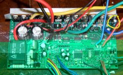
> The most clear indicator of this is that your TVS are 62V rated, and these are present only to protect your FETs.
the 62V nominal TVS can go up to 90V during a 23A spike like the one you'd get on max torque regen, so good design practice would dictate 100V FETs.
> Another thing is that your main bus caps are 63V rated on both models.
the big alu cans, yes, the smaller ones are 100V. my understanding is that alu cans are insensitive to spikes. at high frequencies impedance goes up (instead of down, as in an ideal cap) as they turn inductive, and so the spike is not really charging the capacitor, there's no energy transfer. this means two things: that the capacitor won't filter the spike obviously, and that the cap doesn't need to be specified for the peak voltage (AFAIK). so 63V caps unfortunately don't rule out needing 100V FETs.
> In my eyes that 0.1ohm resistor hack is a quick fix for a poor PCB layout.
IMHO they are there to prevent forward conduction on the unilateral TVS'es (FET body diodes will take almost all the current with the resistors, but not without them).
> film caps ... Epcos ECQ-B1104JF ... AVX ffv3
thanks, I'll have to research these capacitor types. though here in Argentina I doubt I'll find anything even medium-tech.
time has came to choose the power supply; I'll have to choose safety or performance, and without adequate data.
all in all I have to say that I'm 99% agreeing with you, I'm sure the 75V FETs would work. now if I could just be sure...
")