Halls sensors giving strange voltage reading across blk to signal wires

ok thanks I will check for it

was wondering if the halls LED test could be switched in, for ex. on a display? I have an arduino dispay for speed, voltmeter etc, would like to switch in the led sequence just to see if they are working if in a field test situation, would that connected in parallel, upset the halls operation I wonder...?
 
If the LEDs are running at a low current, like under 5mA, it should work OK to have them permanently attached. You could also feed the hall signals to an Arduino with no effect at all. You could use digital inputs.
 
my arduino is crowded now with so many things, maybe Ill just put some leds on a display and switch them in as needed to check when there is an issue

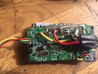
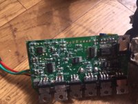
I dont see any small ignition wire on my controller; the key switch just switched the red hot and that red is fed directly into the board, please see reference pics. Im making a new wire set with connectors for the motor halls, thats why they are cut
 

Attachments

  • IMG_6520.JPG
    IMG_6520.JPG
    69.1 KB · Views: 560
  • IMG_6521.JPG
    IMG_6521.JPG
    62.2 KB · Views: 560
OK, some controllers don't have the ignition wire. Yours is one. The resolution of the pictures is not quite good enough to trace things out.
It looks like a pretty crude circuit. A new controller that size is very inexpensive.
 
yes new controllers are an option when I get the money

so what limits the speed, the controller or the voltage? I topped out at about 30 KPH,

also, can the arduino be used as a controller? I has several PWM outputs and an ADC, Im guessing its allot more complex than that, for ex. commutation sensing etc
 
newbiehere said:
yes new controllers are an option when I get the money

so what limits the speed, the controller or the voltage? I topped out at about 30 KPH,

also, can the arduino be used as a controller? I has several PWM outputs and an ADC, Im guessing its allot more complex than that, for ex. commutation sensing etc

The top speed is limited by the voltage but could also be limited by software to comply with some regulatory requirement. You can usually tell by comparing the no-load top speed with the loaded top speed. If they are the same, then the software is imposing a speed limit.
 
Thanks for your reply

for the voltage on the MOSFET gates, normally I see Vgs at 5 volts, for a digital gate input, say for example an arduino digital pin is driving a MOSFET for motor control speed, but for brushless motor MOSFETS, I see allot of
examples where the gate is at the same voltage as the power rail in an enhancement mode N channel MOSFET config. why are the gates at such a high voltage, as in my case, 13.5 volts?
 
It depends on the specific FET used. Some can be fully on at 5v gate drive, but many of the ones we use on controllers won't reach their minimum on resistance until the get up to 8v or so. Driving them at 12v ensures they are fully on. They blow up at 20v.
 
Back
Top