Lessss
1 MW
hmm... I'm getting 54 v at the charge port and dicharge port, but voltage drops to 6v when I plug it into the bike. Time to quadruple check the wiring and connections before bypassing the bms.
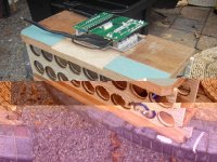
dnmun said:haven't decided exactly how i will make the connections in series. i have some lugs, but may make and solder wire loops on end of the 12G solid wire connector, and attach the sense wire at the same time. it will take a few days to set up so i will look into it.


From what KAE said, the BMS he sells is not headway, and look nothing like the headway we got, so they're something else.Lessss said:From Kenalten.com (Headway) They are sending a replacement.
Lessss said:hmm... I'm getting 54 v at the charge port and dicharge port, but voltage drops to 6v when I plug it into the bike. Time to quadruple check the wiring and connections before bypassing the bms.
frodus said:From what KAE said, the BMS he sells is not headway, and look nothing like the headway we got, so they're something else.Lessss said:From Kenalten.com (Headway) They are sending a replacement.
pvorlicek said:frodus said:From what KAE said, the BMS he sells is not headway, and look nothing like the headway we got, so they're something else.Lessss said:From Kenalten.com (Headway) They are sending a replacement.
Travis:
I was part of your May group buy (just got around to building my pack this weekend). Just built my pack and having a problem similar to Lessss' problem (54V ... then a few Volts when I connect it to my bike). If the BMS turns out to be the problem, how can I get a replacement?
Also, I had one cell that checked in at 2.2Volts (I'm not using this battery in my pack ... it was an extra). Any practical way to get a replacement for this one?
Any info would be very helpful.
Thanks,
Preston
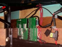
dak664 said:It's not clear from your pictures where the medium black wire from the BMS is connected (not the really small black sense wire which goes to battery minus). I use that medium wire as the charger minus input, with charger plus going to physical battery plus.
Did you put a voltmeter on the header pins and verify the voltage goes up by 3.3 as you buzz up the row? I like to clip the voltmeter minus to the physical battery terminal and use a sharp voltmeter plus probe on the header, less chance of shorting two pins that way.
Well I think that is wrong. The heavy wires are doubled on each side for extra current, one pair is to pack minus out and one pair to battery minus in/out. The medium black, on the same side as pack minus out, should be charger minus input. At least that is what is working for me.pvorlicek said:There are 5 black wires coming from the BMS: 2 heavy guage from the B- side and 2 heavy guage plus one "medium wire" from the other side of the BMS. I am NOT using the medium wire to go to the charger .... I am using one of the heavy guage wires to go to the charger.
You got a BOX! I am jealouspvorlicek said:On the BMS ... let me get this straight: this thing comes with absolutely no documentation, in a plain white box (no markings) ... not sure if there are any real markings on the item itself ... and you want me to believe this thing was FULLY tested before shipment. Sorry, I've been in the electronics business for some time and this has all the "markings" (no pun intended) of a poor quality operation. No respectable QA persion would allow anything to be shipped out like that. I suspect they did some limited basic test.
") . Both of my 12 cell BMSs from the group buy were in pink bubble wrap bags, and are working.
. Both of my 12 cell BMSs from the group buy were in pink bubble wrap bags, and are working.dak664 said:Well I think that is wrong. The heavy wires are doubled on each side for extra current, one pair is to pack minus out and one pair to battery minus in/out. The medium black, on the same side as pack minus out, should be charger minus input. At least that is what is working for me.pvorlicek said:There are 5 black wires coming from the BMS: 2 heavy guage from the B- side and 2 heavy guage plus one "medium wire" from the other side of the BMS. I am NOT using the medium wire to go to the charger .... I am using one of the heavy guage wires to go to the charger.
dak664 said:You got a BOX! I am jealouspvorlicek said:On the BMS ... let me get this straight: this thing comes with absolutely no documentation, in a plain white box (no markings) ... not sure if there are any real markings on the item itself ... and you want me to believe this thing was FULLY tested before shipment. Sorry, I've been in the electronics business for some time and this has all the "markings" (no pun intended) of a poor quality operation. No respectable QA persion would allow anything to be shipped out like that. I suspect they did some limited basic test.
There are markings on mine for the black wires, but they are covered up by the white RTV.