
Hi,
Maybe someone can help to identify wiring on the display? Kid dropped the scooter and all command wires got broken.
It's an old scooter. No marking on it - nothing.
24V. Has break and throttle levers. 3 speed modes. Switch between speed modes by pressing once on the button.
Display shows level of throttle and level of brake on sides.
Also shows odometer, trip and voltage (to switch between them you need to hold button for a little bit, then second quick click)
3 button clicks to turn on/off the headlamp.
I think it's from UK or Europe as the distance is in km and speed is in km/h.
Also found this one in the UK shop, but support is not helpful - old scooter, nobody knows what it is.

 www.segbo.co.uk
Display is in the round casing, one button aside for all operations. Lenzod and V11-20171913 - the only marks on the board.
green/blue wires form the controller feels like rx, tx.
As three others (red, black, yellow) are on a separate connector from the controller and power related (28V between yellow and black and also between yellow and red. nothing between red and black - so the yellow is + then?) - these are colors on the controller connector.
On the display board these controller wires go to 5 pins on P1.
The middle one (currently black wire) connected to the right pin of brake/throttle (P3 and the one above Lenzod logo) and for these both the wire colors are (from the left pin) - black, yellow, red - so red is ground??? (connected to big areas on the board)
The currently yellow one from the P1 goes to the button (leftovers of it are on the left of CS1621CGO chip).
Another side of the button connected to the middle of P1 (currently black) so when you press the button it connects 3rd (black) and 5th (yellow) pins.
It was a fully functional scooter till that incident
Maybe someone can help to identify wiring on the display? Kid dropped the scooter and all command wires got broken.
It's an old scooter. No marking on it - nothing.
24V. Has break and throttle levers. 3 speed modes. Switch between speed modes by pressing once on the button.
Display shows level of throttle and level of brake on sides.
Also shows odometer, trip and voltage (to switch between them you need to hold button for a little bit, then second quick click)
3 button clicks to turn on/off the headlamp.
I think it's from UK or Europe as the distance is in km and speed is in km/h.
Also found this one in the UK shop, but support is not helpful - old scooter, nobody knows what it is.
E-Scooter EX400 Foldable Electric Scooter – Colour LED Screen
E-Scooter EX400 Foldable Electric Scooter. Colour LED Screen for information display. Powerful Silent 250w motor. 5.5inch Tyre Size. Free next day Delivery.
www.segbo.co.uk
Display is in the round casing, one button aside for all operations. Lenzod and V11-20171913 - the only marks on the board.
green/blue wires form the controller feels like rx, tx.
As three others (red, black, yellow) are on a separate connector from the controller and power related (28V between yellow and black and also between yellow and red. nothing between red and black - so the yellow is + then?) - these are colors on the controller connector.
On the display board these controller wires go to 5 pins on P1.
The middle one (currently black wire) connected to the right pin of brake/throttle (P3 and the one above Lenzod logo) and for these both the wire colors are (from the left pin) - black, yellow, red - so red is ground??? (connected to big areas on the board)
The currently yellow one from the P1 goes to the button (leftovers of it are on the left of CS1621CGO chip).
Another side of the button connected to the middle of P1 (currently black) so when you press the button it connects 3rd (black) and 5th (yellow) pins.
It was a fully functional scooter till that incident
Attachments
-
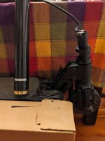 photo_2024-12-08_21-29-23.jpg186.6 KB · Views: 17
 -
 photo_2024-12-08_21-29-20.jpg127.7 KB · Views: 20
 -
 photo_2024-12-08_21-29-10.jpg190.6 KB · Views: 21
 -
 photo_2024-12-08_21-29-07.jpg111.3 KB · Views: 22
 -
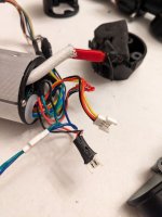 photo_2024-12-08_21-29-04.jpg133 KB · Views: 24
 -
 photo_2024-12-08_21-29-01.jpg199.3 KB · Views: 23
 -
 photo_2024-12-08_21-28-59.jpg158.6 KB · Views: 20
 -
 photo_2024-12-08_21-28-57.jpg162 KB · Views: 19
 -
 photo_2024-12-08_21-28-54.jpg106.7 KB · Views: 19
 -
 photo_2024-12-08_21-28-49.jpg191.4 KB · Views: 16
 -
 photo_2024-12-08_21-26-15.jpg191.8 KB · Views: 15

