Guys. I made first run yesterday evening, and can say that motor is very good. No one bridge can stop me! ")
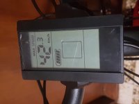
Speed 35km/h and 37km/h top speed. But measure with gps, it's been little lover than that.
Going up on bridge with minimum 31km/h
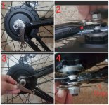
Feel some vibration when starting, think they come from motor, maybe when battery is low, don't know, but ok.
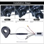
No PAS installed yet.
For now e-brake seems don't needed.
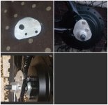
Can someone tell me which chance are to wheel drop out? Is there real happening?
When it's happening, on start or in speeding? I think will be at start because motor use force, or hill.
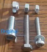
(My torque arm is on the way).
Speed 35km/h and 37km/h top speed. But measure with gps, it's been little lover than that.
Going up on bridge with minimum 31km/h
Feel some vibration when starting, think they come from motor, maybe when battery is low, don't know, but ok.
No PAS installed yet.
For now e-brake seems don't needed.
Can someone tell me which chance are to wheel drop out? Is there real happening?
When it's happening, on start or in speeding? I think will be at start because motor use force, or hill.
(My torque arm is on the way).