caleb7777
100 W
I need the help of some gurus here!
I want to make a small circuit or something that will interrupt the 5v+ on the throttle for 50 ms. (or whichever line will cause 0 throttle output)
I am designing my new ebike with the star delta switch which changes the phase motor winding configuration. see here:
http://endless-sphere.com/forums/viewtopic.php?f=2&t=9215&start=120#p149061
my Cycle Analyst will control when the relay switches to the higher speed delta config.
At a set speed the CA will send a ground signal to a 5v relay I have which will then power the larger relay that switches the phases over.
the relay switching is supposed to take 30 ms with these relays.
It would be desirable if the switch always took place while the throttle was at rest so that the phases were not under as much load which is the purpose of this circuit.
I want a circuit that disconnects the throttle for 50 ms when the CA first sends the ground signal and for another 50 ms when the ground signal ceases.
This will allow no load when the relays engage and disengage automatically.
Help please guys!!!!!
OK so I have 2 working units!
These are still beta as I have not actually used them on a bike yet but test out as they should. They run on a 12v supply when using the LM7805 because DC-DC converters of this voltage are easy to find and cheap.


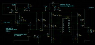
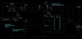
Design recommended by Rick using a 556 timer is No. 1 and the second is a circuit using a 4098 IC as an edge trigger. The second does use less power and is simpler however I noticed that it does activate oddly in one direction and appears to fire twice rather than once. I actually saw the test LED fire twice with fast pause in between. This might be fixed by a dampener somewhere but I wouldn't know. But this doesn't really affect the operation as it will still take only up to half a second for throttle to re-engage. if it worked great in both directions one could expect 150 ms throttle cut off in each direction. But as it is it might be double that when shifting back down to WYE. Which is fine.
The 4098 instructions I found called for t=0.5RC on the timing circuit attached to the 4098 so I drew it up as 150nF and a 2Mohm resistor which should then give approx 150ms.
I don't have an oscilloscope or any way to test times this small so my beta rig used very high timing constants on the left relay x1000 to find the appropriate resistance and capacitance for that relay to get ~45ms open and close delay. These values only apply to this relay.
This is the relay I used there: Aleph SD1A05AWJ 5V DC 1A View attachment Aleph SD Series.pdf
Different relay would most likely require slightly different values which you would need to test for.
And most important is a big shout out to Rick (rkosiorek), fechter, and methods on Endless-Sphere.com, and bernard on allaboutcircuits.com for all the help and tips to help this circuit live. Thank you guys. Especially Rick.


