Help needed troubleshooting Infineon controller

Hugues

1 kW
Joined
Aug 7, 2011
Messages
434
Location
Switzerland
Hi guys,

i'm troubleshooting my spare controller, it never worked since i received it, infineon 40A, exactly the same as my current one, same board.

Here's what i've done so far / what i've seen:

- with my current controller my bike is working perfectly fine
- so i just swapped the controller with my spare one, all the rest remains the same
- phase and hall colors match on both controllers
-i tried with and without Cycle Analyst connected, same results
- Cycle Analyst displays proper voltage
- i measured the voltage on different points of the board, can't find anything wrong, 82 V is there between VB- and VB+, 5v and 12V bus is ok, halls sensors flip between 0 and 5 V when spinning the wheel, throttle pin on the board goes from 0.8V to 4.2 or something when i twist the throttle. The BRK pad has 5V on it, so no brake switch activated here.
- before powering the board i checked the resistance between all pins of all FETS, they are all ok now, i had to change 2 last week.
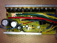
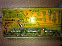
- I know the soldering look suspicious, but i inspected them carefully and there are no shorts nor bad connections.
- there is no abnormal resistance when i spin the wheel
- i don't know about the caps, i don't know how to test them, visually they look ok.

Any other idea what i could test ? I'm running out of ideas here... :(

thanks for your help,

front.jpg
back.jpg
 
Sorry, but I an't be any help I am afraid.
i am after similar troubleshooting info for my sensor less controller...will do a new post for that

I see in your sig that you have a magura brake switch

could you make a comment on it for me on a thread I created?

http://endless-sphere.com/forums/posting.php?mode=post&f=2
Thanks
 
What's the voltage at the throttle 5V supply? DoctorBass had a hard to identify failure of a small item on the Infineon board whose only symptom other than not working is a lower than 5V supply on some of the 5V rail.

Other than that it, maybe it's a program issue. Are yours set up for programming? That's something you're definitely qualified to DIY if not, and all the info needed is in those monster Infineon threads.
 
thanks John,

i'm definitely going to check that later this afternoon after my daily ride, weather is real nice ,

form what i remember last night it was not 5V exactly everywhere, i will measure and report this, i think I remember the thread from DrBass...

I've not attempted to program my controller, at least not yet, i'm pretty much able to screw things up without even playing on that ground, he he,but time will come.
 
pity you're on the other side of the country else I could have a look for you

I'm wondering whether you FETS turn on, and if they do, whether they are
really low ohmic.

to test: give it full throttle, slowly turn the wheel so the hall sensors toggle and
measure the voltages that the controller sends to the motor. These should toggle
in the same rithm as the hall sensors but have the full battery voltage behind them.

if this works, connect light bulbs (220V ones will do) between the 3 power wires
to the motor to see if they (weakly, you only have 80V) light up (this is a check to
see whether you output stage can still deliver reasonable current).
 
Lebowski said:
pity you're on the other side of the country else I could have a look for you

I'm wondering whether you FETS turn on, and if they do, whether they are
really low ohmic.

to test: give it full throttle, slowly turn the wheel so the hall sensors toggle and
measure the voltages that the controller sends to the motor. These should toggle
in the same rithm as the hall sensors but have the full battery voltage behind them.
....
Hi,

Thanks for the offer, much appreciated.

i was wondering too, if they are alive or not, did not know how to test, thanks

the first test above i do with the phase wires disconnected from the motor but the halls connected, right ?

going to ride for a few hours now, sun is up and shinning...
 
ok, performed some more tests this afternoon, here's what i've got:

- Output of 5V reg is 5.0 sharp
- but readings on other 5v pads on the board give 4.2V, so is the throttle input.
Could this be a problem ? Throttle output varies from 0.8 to 3.6 V, so i guess all ok on throttle side.
Any other components using 5V bus that could not work well at 4.2 V ?

- I've performed the test proposed by Lebowski, i get 0 V reading on 3 phases while spinning the wheel slowly.
- I also checked halls signals-in on the board and they flip between 0 and 5.0 V nicely.

- After reading NeilP's thread today, i checked resistance between FET's tab and heat sink.
At first i thought i found the problem because i had only 312 ohms on last 2 FET while others were giving infinite reading.
I unscrewed both of them and separated from the heat sink, resistance changed to infinite, i could see the small film is torn apart a bit.
But unfortunately i re-tested the whole thing with this setup but no change, still no voltage on phases.

Any other ideas are welcomed. Remember that hub is running fine with other controller. So the problem is definitely with my spare controller.
 
Ok, looks like the FETS are not switched on / off, let see if the gates
of the FETS are driven correctly (assuming of course you measured
correctly and had a battery connected in the earlier measurements ?)

Find out what fets you have (4110 ?). Go to http://www.farnell.ch and look
for the datasheet of the FETS. In the datasheet you can find which wire
is the 'gate' and which wire is the 'source' of the FET. Measure between
the gate and the source of the FETS (the gate is positive). As you slowly
turn the wheel to activate the hall sensors the gate-to-source voltage of
your FETS should switch between 0 and something like 12 Volts..... ?

99% of the time the tab is connected to the 'drain', this is either the left
or right side of the 3 pins of the FET. The middle is typically 'source' and the
one on the other side the 'gate'
 
positive, battery was connected, checked all connections twice.

Bought those FET at Distrelec.ch:
https://www.distrelec.ch/mosfet-to-220ab-n-100-v-120-a/ir/irfb-4110pbf/605101/fr

Found those specs from the farnell web site you gave me.
http://www.irf.com/product-info/datasheets/data/IRFB4110PBF.pdf
I've got 4 of those on the board, other 8 are original ones i got from ebikes.ca, cannot quite read the type they are, i'm not even sure there is something written on them.

So that's Gate, Drain, Source from left to right.
Drain is on tab.
Will test that tonight.

YOu say the Drain is on the right or left side 99% of the time. But those i installed seems to have the Drain on the middle pin ?!?
That could be my problem ? I wonder which FET the originals are, maybe they have different connections ?
I need to dig into this, i will get back to the garage and try to read which model they are, unless someone with Infineon knowledge knows.

speak to you later
 
I have just today looked at two different Xlyte controllers..and Drain is middle pin on them. IFRB 4110 also
But.. when I built my CC/CV board for the Meanwell charger....BC107's ...the ones I received were different form the ones originally used..the pinout was different..the difference was some were BC107C and some BC107A...so double check the part numbers are exactly the same just in case something similar has occurred in the part numbering
 
Lebowski said:
.... Measure between
the gate and the source of the FETS (the gate is positive). As you slowly
turn the wheel to activate the hall sensors the gate-to-source voltage of
your FETS should switch between 0 and something like 12 Volts..... ?

...
ok, done that

none of the 12 FET show 12 V between gate and source when i turn the wheel slowly. Reading is zero.
I checked again that the board is powered and halls signal-in flip between 0 and 5 while doing that.

There is nothing written on the other 8 FET by the way, can we suppose drain is middle pin ? I guess so.
 
at this point you need a schematic. Either you micro controller doesn't give any output, the circuit
amplifying the 5 V microcontroller output to 12 V is broken or there is no proper 12 V.

Do you have the schematic so I can have a look ?
 
Hi,

measured the voltage from the entry on the board,
- i see 78 V on the main, my battery was pretty much discharged
- then slightly below before entering the first regulator, 74 V, then output 14 V
- 14 V goes into the 5V regulator, output is 5.0V

:(
Everything seems ok there, i checked the voltage on the microprocessor, 4.5 V, i guess it's ok.

I don't have a schematic unfortunately, but i think i'm going to stop here.

I PM Justin so that he can read this thread if he has time, maybe he's going to tell me what to do next.

It's quite expensive to ship the controller to ebikes.ca for check and repair, then back here, I'd better buy a new one and keep this one for spare parts i guess.

we'll see

and thanks for your time and guidance
 
once I finish my highly advanced (etc etc etc :D ) controller you can mail it to me,
I'll do a brain transplant :D you'll be riding the world most advanced bike then.

If the 14V is there either the processor is broken or the gate driver circuits...
 
Back
Top