help review custom torque arm design

curious

1 kW
Joined
Dec 29, 2007
Messages
445
Location
NJ, USA
I've got a recumbent frameset (aluminum) and I want to make a DIY rear torque arm to make sure I never get a spinout - it would be way too costly. My metalworking abilities are limited to a drill press, dremmel and basic hand tools. After some thought I came up with the following design:
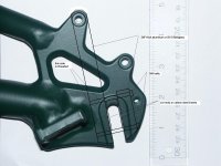
dropout1_ta1.JPG
Few notes:
- It will be used with medium power 9c setup.
- There is little space to do anything on the derailleur side and no strong attachment points. So the plan is for one side arm.
- My first thought was to make a single piece arm from stainless steel but drilling/cutting/threading thick hard steel is probably outside my abilities. I think a better approach would be to make the arm body out of 3/8" thick hard aluminum alloy or G10 fiberglass and use a pair of hard steel inserts (chromoly or carbon) at least 1" long to protect the arm material and spread the load. I can cut inserts from 3/8" wide x 1/8" thick x 1" long hard steel bar with a dremmel tool and add two notches for the bolts so the stack stays properly centered during assembly.

Folks, if you have some mechanical design experience, could you please review the pictured design ?
 
Your idea of mounting the torque arm directly to the disc brake hole is nice. However I think aluminium or fibreglass will be too weak in your design. You need high strength steel not only at contact points, but also to transfer the force. I suggested to ebikes.ca that they make a torque arm with the axle part pre cut and just a straight steel extension where the user drills a hole to match a disc brake mount or other mount on their frame. However, ebikes thought frames were too variable for this to work. I'm using the ebikes.ca front fork torque arm on the rear. It reaches to the lower disc brake mount using their intermediate arm. With a join on the middle it is not as strong as a one piece, but hopefully enough.
TorqArmRev2.jpg

Another option that might work is the amped bike arm:
torque.JPG
 
I have considered these and many others. I can not prove it but looking at the wear stress points on the steel arm that I have on the other bike, the rocking motion eats the contact point in no time (I have regen setup). I have not had any issues with the remote attachment point, nor with the strength of the arm body. Hence I want the arm with compression mechanism preventing ANY movement beyond what is allowed by elastic deformation of the axle/arm body.

BTW I meant hard aluminum alloy of course, not pure aluminum for the arm (or perhaps G10) 3/8" to 1/2" thick so it provides sufficient support for contact point plates. It can be much thinner near the disc brake mount point but I have no milling equipment to do custom lightweight profile.
 
I have a 9C also. 7x9@72V, about 2kW peak, but I don;t do regen.

If you have rocking I agree that is a bad thing. I was lucky in that my frame has beefy forged dropouts and the axle fit is very tight to start with (have to tap it in).

Do you have large diam torque washers or regular washers on both sides of the dropouts already? Washers can help I think, by transferring the torque over the whole surface with a much larger diametre than the tiny axle contact point on the inside, or the not so big contact point of the axle nut.

With your design I would wonder about both the strength of the arm at the top through bolt, as well as the strength of the threads holding the bolt. Even if you get a high grade bolt, the max holding force in aluminium is not so high.
 
My current ebike has x5 hub in a chromoly frame with high power regen controller. The torque arm never failed but will need to be replaced at some point. The new recumbent I am building with 9C hub exists as a frameset, wheels and a box of parts for now, but considering the cost of the frameset I have to make sure the axle will not spin.

The torque induced force applied at the axle flat contact point is over 10x higher than the force at the end of the torque arm. The top bolt will be threaded either in a steel lock nut or in a brake caliper (for now I plan v-brake in the rear but that may change). The frame itself will not be threaded. At least part of the torque force will be frictionally coupled to the frame at the top. But I do see your point - I may need to think over the top attachment. There is a round depression in the frame that can be used if I could weld a conically shaped spacer/washer to the arm but I have no welding equipment, especially for aluminum. Perhaps using a separate spacer/washer made from a high friction material and fitting the depression would do.

As far as the arm body strength - I am not sure it is an issue. If the local stress is mitigated then a 6061T or better 7075 bar with a cross section of about 3/8"x1/2" should hold I think.
 
7075 alloy is aircraft grade and may be strong enough in a 3/8 section. The problem is the failure mode of alloy. Perhaps check out Dr Bass and his torque arms bonded with epoxy or John in CR with compression bolts. All IMHO. Sounds like a great project. Pictures? I believe yours are of the existing dropout. I have an inherent fear of alloy and high torque electrics to the point where we were considering a Kettweisel for Joyce but I wouldn't dare as the forks are alloy. The price difference in this case was not an issue.
otherDoc
 
I like the design, but not the aluminum. You're right a clamping dropout is what you want and is worlds better than any of the store bought stuff. I understand you're limited in metal working tools, but with a length of 1/2" square stock you could just use a hacksaw to make one cut to make the 2 pieces, and drill and tap your holes, or have the place you source it cut the 2 pieces for you. 3/8" steel or maybe even 1/4" could work if you can go with at least 1/2" wide for the contact surfaces on the axle. How much axle do you have to work with on that side?

4mm bolts seem too small to me, I'd go with 4 of them.
 
docnjoj said:
Pictures? I believe yours are of the existing dropout.
That is the actual dropout on a recumbent frameset that I got. I will post pictures as I go - there is a lot of work ahead and little time...
 
Somebody in NJ gotta have a bandsaw and a drillpress!
otherDoc
 
John in CR said:
I like the design, but not the aluminum.
I would never consider aluminum without stress relieve inserts. I can cut relief inserts easily with a dremmel tool from a standard bar of tempered hard steel, much harder than usual SS stuff. I imagined suffering drilling and threading 1/2"+ deep holes in SS and that thought turned me off :) I can try making the arm a bit wider instead.

John in CR said:
3/8" steel or maybe even 1/4" could work if you can go with at least 1/2" wide for the contact surfaces on the axle.
The plan was for 3/8" thickness arm parts and matching width of hard plates so the whole thing can still be compressed with an axle nut. I need to measure the length of an axle past the frame for exact answer.

John in CR said:
4mm bolts seem too small to me, so use 4 of them.
That is preliminary, but there is a trade-off how much material you want to remove from the arm, because it is precisely where it will break.
 
docnjoj said:
Somebody in NJ gotta have a bandsaw and a drillpress!
I have a friend with a drill press, but drilling hard SS is not fun even with a good drill bit and cooling :)
 
The stainless that I have worked with is drillable if you take your time. The cutting and shaping is the problem and it is better than hard carbon steel. Also consider SAE grade 8 bolts instead of metric as they are substantially tougher. I have spun steel dropouts with geared motors and DD and know the dangers of aluminum. Those high torque motors are difficult to hold on to! Good luck with your enterprise!
otherDoc
 
Mild steel is fine. That's probably what the axle is made of, so anything harder is of no benefit. The width of the contact area with the axle flats is what's important. Weight isn't an issue, since even a total of 5" of 1/2" square stock would weigh less than 6oz. In addition to simplifying construction, another benefit of going all steel is that you could bend the long piece to get a perfect alignment with the bolt hole at the top.
 
The idea looks good, but as others have said I'd go with steel rather than aluminum, solely because aluminum will break rather than bend in a failure, and usually it is a sudden catastrophic failure with no warning (unless you are performing some pretty high levels of scrutiny upon it before and after each ride, on the level of that of aircraft maintenance).

I didn't really understand the problem with aluminum breaking this way until I began experiencing it with various things I have been building for my ebike and cargo stuff, and examining pics of various failures others have had. But having witnessed it, I would not use aluminum in a critical part like a torque arm, especially if it's purpose is to protect other aluminum parts.

The harder the aluminum is, I think the more likely it is to give no visible warning before failure (even though it will take that much more stress before the failure).

With steel, at least you will probably have visible bending before a failure, giving warning if you are performing regular inspections.


Regarding the rocking you see in your other setup, that sounds quite bad. Does that happen even with tight axle nuts, etc? If so, I would want to replace the torque arms on it with a different type, such as these clamping ones you are designing, so that there can be no tiny gap to start the rocking wear process.
 
Ok guys, you almost convinced me :). I am going to order both SS and 2024 aluminum alloy bars (3/8" thickness, 1/2" width) http://www.onlinemetals.com can do custom lengths so I can avoid cutting SS altogether (if I can live with ugly rectangular shapes), only drill and tap it.

I will try SS arm first. If I fail to drill SS then I will fall back to alloy+plates option. 2024 aluminum alloy apparently has the highest ratio of ultimate tensile strength to yield strength (among hard alloys) which means it should be less prone to catastrophic failure (break). And I can shape it into something much more aesthetically pleasing than SS.

For SS option I'll get a high-tensile strength M5 bolts for the main clamp. For 2024 M4 is probably the maximum for 3/8" thick arm - bolt hole/thread is obviously the weak point of the arm. Top bolt will be M6 to maintain compatibility with disk brake hardware if I ever go that route.

Regarding drilling SS. Did some search, apparently I need few cobalt bits, low rpm, high pressure and some coolant. I found the bit sizing table for tapping metric threads so I think I am set.

Thanks everyone for useful comments. I will post pictures if/when I am done :)
 
Update - making the arm was much faster than procrastinating over the design and finding/ordering the materials/tools :). I ended up using 0.5"x0.5" 304 SS square bar pre-cut to my dimensions by http://www.onlinemetals.com so I only had to file off rough edges and drill/thread the holes. Drilling SS using low speed, cobalt bit and lot's of coolant was nowhere as bad as I expected. All bolts are M6 (12.9) with a rubber tube in the gap for bolt rust protection and some spring action. The arm is kind of heavy at around 200g but I can live with that for now. I still think 2024 alloy is strong enough for the mid-power setup and obviously much lighter but weight reduction can be done later.
 

Attachments

  • ta2.JPG
    ta2.JPG
    12.1 KB · Views: 3,794
It's not that alloy isn't strong enough. It's that alloy is not meant to be put under the pressure of clamping. Under stress is fails much easier, which is the same reason you should try to spread AL dropouts more than just a little to fit a hub motor between them. Also, with the repeated force of the axle trying to twist one way and then the other way with regen it's not a matter of if it will fail, but when it will fail, which will occur without warning.

If you really want to trim some weight, just take material off the long bar. Away from the clamp you could remove over half the steel (even more toward the end) with no effect on strength. Round off the square corners except in the clamp too, and you could easily lose half the weight and improve the aerodynamic effect, which is far more than the weight, though both are minuscule.

John
 
amberwolf said:
So how well does it work?
The recumbent I am building is still in the works. I am getting all the pieces for the electric conversion while still enjoying it as a pedal-only bike (while the weather lasts). I did however try to mount it on the hub axle and it holds perfectly as far as I can tell. I'll update the thread again when I put everything together and test it.

John in CR said:
If you really want to trim some weight, just take material off the long bar. Away from the clamp you could remove over half the steel (even more toward the end) with no effect on strength.John
I had this thought. If I find someone with a quality band saw or a mill nearby I'll take half the thickness from the arm (except for the clamp area), but there is no rush to do it. Eventually I want to get some metalworking tools myself (minimill, band saw, grinder) but I've been renting since 2k3 and moving heavy machinery is not an exciting proposition :).
 
That is a clever looking torque arm. I'd use loctite on the screws instead of the rubber. SS is good stuff.
otherDoc
 
If you're referring to Curious' design, there isn't a hole for the axle, as that gets trapped in the flats between the bolts.

If it's another design you're talking about, you'll have to attach a picture of it.
 
I hope this isn't off topic:
I'm trying to make a longer torque arm to reach the rack mounting hole
 

Attachments

  • TorqArmRev2.jpg
    TorqArmRev2.jpg
    22 KB · Views: 3,719
Nanoha, when I first decided to make my own torque arms several years ago I got a course round tapered file that is about 3/8 inches at its greatest diameter. I first drill a 3/8" hole and then slowly file it out to fit the axle flats. By slowly, I mean test fitting frequently.

I've made at least a dozen torque arms with this technique and the file is still in good condition, but all were using regular steel, 1/8" to 1/4" thick, no stainless. None of the torque arms ever failed or showed any wear, and some were used in plug braking applications, but the highest power was only 48V by 35 amps.
 
Nanoha,

With a lack of machining tools, I'd start with a 9mm bit on a drill (assuming 10mm flats) and once the hole is drilled I'd tilt the bit back and forth to create the longer dimension. Then finish up the rounded ends with a round file and the flats with a flat file.

I believe a clamping dropout is significantly better to eliminate any play between the axle and torque arm. Using the 2 piece 2 bolt method in the original post, it is even easier than trying to drill and file out the odd shaped hole in the non-clamping kind. All you need is 2 pieces of steel, clamp them together, and drill the bolt holes.

I'm kind of partial to the 1 piece 1 bolt clamping type, because even if my bolt came loose and fell off I'm still left with a very thick dropout the fits the axle snugly. I'm not the type to just get on and ride without any kind of pre-flight checklist routine, even a monthly check, so I need to build stuff as failure proof as possible. eg In a 19months of daily use, I checked the hubmotor axle nuts on my daily rider maybe twice. A one piece build is a bit more involved, but can still be done quickly with very basic tools such as.
clamping torque arm.JPG
Drill the green holes with a drill.
Cut the red lines with a hacksaw and clean it up afterward with a flat file.
Make the blue cut with a hacksaw with doubled up blades to make the cut a bit wider than a single blade to allow for absolutely secure clamping.
 
Back
Top