Help Wanted - Wiring Lights

xanderstone

1 µW
Joined
Jun 13, 2025
Messages
4
Location
South Florida
Thanks for taking the time...
I'm new here and new to electric bikes in general. I bought an electric pit bike which has no lighting nor does it have accessibility to the controller plug/dongle due to it having been waterproofed.
I went and bought myself a cheap 12v brake and turn signal setup and a dot approved headlight.
Sadly my inexperience has led me down a rabbit hole.
The components I have are the lights, a switch, and a 48v-12v converter. I will post links if needed.
The headlight has the standard Harley plug, 4 wires. The tail and blinkers 3 wires.
From my understanding, the DC converter taps into main power from the battery. The lights then connect to the converter and are grounded to the neutral. The brake light needs to operate off the motor stop switch already part of the bike.
This is what I see in my head as correct for this all to work but it being my first time, I'd like a more experienced person to help break me into this.
Thanks again for your help.
 
The connections to your current setup are the battery, connecting to your buck converter, and between the brake cuttoff circuit and the brake light input.
For the former, you may elect to add a switch so you can turn off the whole lighting system, since the buck converter will always have a small drain on the battery if not disconnected, even when the lights are off.
On the latter, you need to provide more info on your controller, since brake lights usually require using the “high brake” circuit rather than the “low brake” circuit.
 
Appreciate your quick reply and info. The controller is a fardriver but the documentation on it is unavailable. The naning PDF is for a different more recent version and it pin outs are very different. KG48v70AB_81_ZH996 is the model of the controller itself. A google search results in just the PDF from naning.
I like the switch idea for absolute off. That would allow me the option for driving lights or none at all plus the regular lights.
By buck converter I will assume it's the DC to DC yes?
To identify the high/low brake could I trace the wires or should I use a multimeter? What would the V be for such a systems high side if I am to test it on the pin out of the controller?
(Your name with the 1TW, does that stand for one terrawatt?)
 
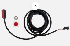
It's probably better not to piggy back off the switch already in your brake levers as it might interefer with the controller circuity. If you don't mind the extra wiring (use a spiral wrap), there are magnetic switches you can attach for a separate circuit.

I prefer to hold the magnet with a screw rather than rely on glue or sticky tape, but the switch body is light enough to be held with adhesive.


switch.jpg
 
It's probably better not to piggy back off the switch already in your brake levers as it might interefer with the controller circuity. If you don't mind the extra wiring (use a spiral wrap), there are magnetic switches you can attach for a separate circuit.

I prefer to hold the magnet with a screw rather than rely on glue or sticky tape, but the switch body is light enough to be held with adhesive.


View attachment 371673
Thanks for the tip. I knew it could cause circuit issues but it as figuring the worst that could happen is the motor doesn't stop when I apply the brake. Lol

So basically run another switch to the handle lever? Easy enough and I don't mind the extra wiring at all.
Thanks again !
 
Appreciate your quick reply and info. The controller is a fardriver but the documentation on it is unavailable. The naning PDF is for a different more recent version and it pin outs are very different. KG48v70AB_81_ZH996 is the model of the controller itself. A google search results in just the PDF from naning.
I like the switch idea for absolute off. That would allow me the option for driving lights or none at all plus the regular lights.
By buck converter I will assume it's the DC to DC yes?
To identify the high/low brake could I trace the wires or should I use a multimeter? What would the V be for such a systems high side if I am to test it on the pin out of the controller?
(Your name with the 1TW, does that stand for one terrawatt?)
Maybe this video will help. Pay attention to connecting the high brake. Basically you’ll tap into the switched high brake signal going to the controller to also power your brake light.

Buck converter is the step down DC-DC (a converter that increases voltage is a boost converter).


I believe TW stands for terawatts. That’s something the forum software adds to indicate the number of posts a user has made, but I don’t know how the scale works.
 
Back
Top