• Hello ES! We could use some help to get us past the finish line on building the new knowledgebase for the forum.
    Can you donate? Please see our fundraising page. Thank you!

Help Wanted - Wiring Lights

xanderstone

🧲 New user
Joined
Jun 13, 2025
Messages
11
Location
South Florida
Thanks for taking the time...
I'm new here and new to electric bikes in general. I bought an electric pit bike which has no lighting nor does it have accessibility to the controller plug/dongle due to it having been waterproofed.
I went and bought myself a cheap 12v brake and turn signal setup and a dot approved headlight.
Sadly my inexperience has led me down a rabbit hole.
The components I have are the lights, a switch, and a 48v-12v converter. I will post links if needed.
The headlight has the standard Harley plug, 4 wires. The tail and blinkers 3 wires.
From my understanding, the DC converter taps into main power from the battery. The lights then connect to the converter and are grounded to the neutral. The brake light needs to operate off the motor stop switch already part of the bike.
This is what I see in my head as correct for this all to work but it being my first time, I'd like a more experienced person to help break me into this.
Thanks again for your help.
 
The connections to your current setup are the battery, connecting to your buck converter, and between the brake cuttoff circuit and the brake light input.
For the former, you may elect to add a switch so you can turn off the whole lighting system, since the buck converter will always have a small drain on the battery if not disconnected, even when the lights are off.
On the latter, you need to provide more info on your controller, since brake lights usually require using the “high brake” circuit rather than the “low brake” circuit.
 
Appreciate your quick reply and info. The controller is a fardriver but the documentation on it is unavailable. The naning PDF is for a different more recent version and it pin outs are very different. KG48v70AB_81_ZH996 is the model of the controller itself. A google search results in just the PDF from naning.
I like the switch idea for absolute off. That would allow me the option for driving lights or none at all plus the regular lights.
By buck converter I will assume it's the DC to DC yes?
To identify the high/low brake could I trace the wires or should I use a multimeter? What would the V be for such a systems high side if I am to test it on the pin out of the controller?
(Your name with the 1TW, does that stand for one terrawatt?)
 
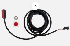
It's probably better not to piggy back off the switch already in your brake levers as it might interefer with the controller circuity. If you don't mind the extra wiring (use a spiral wrap), there are magnetic switches you can attach for a separate circuit.

I prefer to hold the magnet with a screw rather than rely on glue or sticky tape, but the switch body is light enough to be held with adhesive.


switch.jpg
 
It's probably better not to piggy back off the switch already in your brake levers as it might interefer with the controller circuity. If you don't mind the extra wiring (use a spiral wrap), there are magnetic switches you can attach for a separate circuit.

I prefer to hold the magnet with a screw rather than rely on glue or sticky tape, but the switch body is light enough to be held with adhesive.


View attachment 371673
Thanks for the tip. I knew it could cause circuit issues but it as figuring the worst that could happen is the motor doesn't stop when I apply the brake. Lol

So basically run another switch to the handle lever? Easy enough and I don't mind the extra wiring at all.
Thanks again !
 
Appreciate your quick reply and info. The controller is a fardriver but the documentation on it is unavailable. The naning PDF is for a different more recent version and it pin outs are very different. KG48v70AB_81_ZH996 is the model of the controller itself. A google search results in just the PDF from naning.
I like the switch idea for absolute off. That would allow me the option for driving lights or none at all plus the regular lights.
By buck converter I will assume it's the DC to DC yes?
To identify the high/low brake could I trace the wires or should I use a multimeter? What would the V be for such a systems high side if I am to test it on the pin out of the controller?
(Your name with the 1TW, does that stand for one terrawatt?)
Maybe this video will help. Pay attention to connecting the high brake. Basically you’ll tap into the switched high brake signal going to the controller to also power your brake light.

Buck converter is the step down DC-DC (a converter that increases voltage is a boost converter).


I believe TW stands for terawatts. That’s something the forum software adds to indicate the number of posts a user has made, but I don’t know how the scale works.
 
Wow thanks again! I was thinking you got yourself a tw bike and was thinking you're crazy lol

Truly appreciate the information and link.
 
Let me add this to my question...

With a switch for the buck converter, could the headlight switch itself be used inline before the buck converter as an on/off?
Battery - buck converter - switch - lights

???
 
Because you guided me with this first time project, I've chosen to create a light circuit separate from the bike using the LI-5 from LiFePO4.
I mocked it all up today and will probably do a write up just for posterity. You all know much more than I when it comes to all this E-bike stuff. I'm just a guy with ideas to improve on whatever I own.
My intent is to run all from the second battery using good fuse before the whole system and to use the horn switch as the brake light switch until my magnetic switch cable arrives. Then I'll wire it correctly. It worked fine during the test and the total amp draw was less than the rated battery.
My only issue is mounting the battery properly. I do not have a metal case to enclosed it into but the bracket holding my controller should accommodate a fabricated bracket for the battery so it doesn't shift or jostle.
While I like my little mid motor Chinese bike, there's very little places to mount anything. Even the wiring will be a challenge to route so the bike looks untainted.
Thanks again for your input and help. I appreciate the guidance and direction.
 
Battery - buck converter - switch - lights
This is how I’ve wired my lights. With the exception of my rear tail light. I have that always on when the bike is on and I feed it full pack voltage (yes, the light is rated for a 12-48 volt power supply). It’s wired before the buck converter.
 
My intent is to run all from the second battery using good fuse before the whole system and to use the horn switch as the brake light switch until my magnetic switch cable arrives. Then I'll wire it correctly. It worked fine during the test and the total amp draw was less than the rated battery.
If you plan on using the magnetic switch to directly activate your brake lights, make sure you pay attention to the specs. The ones I got from Amazon state 5w dc as their rating (under normal use, the controller only needs a signal input, so current is minimal).
 
This is how I’ve wired my lights. With the exception of my rear tail light. I have that always on when the bike is on and I feed it full pack voltage (yes, the light is rated for a 12-48 volt power supply). It’s wired before the buck converter.
I know I could use the buck converter and run it always but I could not wait for the converter to arrive so I went and got the separate battery. I am still a kid sometimes and act impulsively. Lol Really I'm running it this way because it won't tax my battery at all which should result in less expense over the life of the main battery.
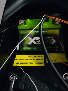
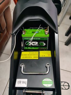
This battery is tiny and light. It fits easily between the battery and the controller bracket.
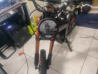
All the wires are run except the headlight and there's only one area where the wiring might show. (Headlight brackets on the way) Soldiering it all will be a tomorrow project. Today was planning, fitment and testing plus a few pics.
 
If you plan on using the magnetic switch to directly activate your brake lights, make sure you pay attention to the specs. The ones I got from Amazon state 5w dc as their rating (under normal use, the controller only needs a signal input, so current is minimal).
Thanks for that. I'll have to test the one I ordered and wait longer if it isn't up to par.
 
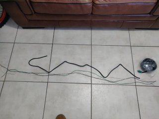
Here a few pics of what I'm into. You've seen/done this before so it's nothing new but figured I'd slap some up so you know I'm not all talk 😂

The headlight is like the spark from a welder. The wires come from a computer power cable and easily provided me the different colors for ease of connecting them. I split the outer shielding with a blade and used it as wire wrap. Yeah cheap and not professional but it looks it. Lol

Thanks again guys for your help and input.
 

Attachments

  • IMG_20250617_180622.jpg
    IMG_20250617_180622.jpg
    1.3 MB · Views: 13
  • IMG_20250617_180523.jpg
    IMG_20250617_180523.jpg
    1.7 MB · Views: 13
  • IMG_20250617_161655.jpg
    IMG_20250617_161655.jpg
    1.4 MB · Views: 11
  • IMG_20250617_161641.jpg
    IMG_20250617_161641.jpg
    5.1 MB · Views: 13
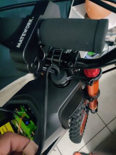
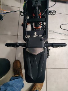
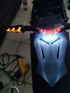
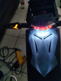
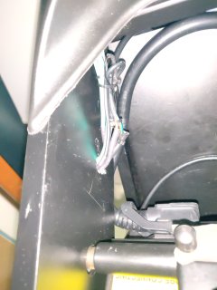
So today I wired up and routed the wires for the brake, tail, blinkers and to my surprise hazards. It looks clean and isn't visible from the outside frame.
The tiny white wire and the two on the left are for the headlight. I'll properly connect the wires to the battery when I wire it up tomorrow. Along with a bus fuse.
Again I appreciate your help making this more fun than aggravating 😂 wiring isn't my strong suit and I had to cut my soldier joints a couple times due to forgetting to slide the heat shrink on.
 

Attachments

  • IMG_20250619_135034.jpg
    IMG_20250619_135034.jpg
    1.6 MB · Views: 4
  • IMG_20250619_135035.jpg
    IMG_20250619_135035.jpg
    1.7 MB · Views: 3
  • IMG_20250619_135051.jpg
    IMG_20250619_135051.jpg
    1.2 MB · Views: 4
  • IMG_20250619_135225.jpg
    IMG_20250619_135225.jpg
    1.4 MB · Views: 4
Apologies for the long delay. Been under the weather.
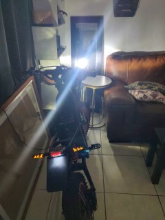
Finally finishing up the light system. It is 95% complete. I took your advice and ran everything to the main with a fuse and buck converter.
Besides soldering all the wiring hiding the them was the toughest part. Ended up going through the frame to keep it clean. Now I'm just waiting for the wire loom to arrive.
For the headlight, my switch has only on and off which seems odd being a motorcycle combination switch but I can live with it for now. Wired up the drv and low beam so it's a lil brighter than just the low beam.
The bike came with a motor cut off built into the rear brake lever so I'm not sure how to add a brake light to it so I opted to use the horn button since I don't intend to use a horn. My voice is louder than those tiny meep keep horns anyway.
It's a bit of a pain but works for now. More research needed to figure out the best option here.
I have to thank you all for the information and tips getting me off the ground with this. I officially ran my first e-bike circuit.
Below are pics in no specific order showing my work. The two switches are controlling the lights, the gray is the power cutoff for the buck and the other funs the light function. Found out by accident that I have hazards if I press both left and right blinker buttons. Score! Lol
Thanks again for your help and knowledge. I appreciate it. Now to go blind some drivers!!!
 

Attachments

  • ed56a706-5362-410f-b088-fa4796e0f9dc (1).jpg
    ed56a706-5362-410f-b088-fa4796e0f9dc (1).jpg
    742.3 KB · Views: 6
  • IMG_20250707_191149.jpg
    IMG_20250707_191149.jpg
    1.3 MB · Views: 5
  • IMG_20250706_164330.jpg
    IMG_20250706_164330.jpg
    5.2 MB · Views: 6
  • 765ee3d7-d306-43ea-8ef4-c6ccd20a41ae.jpg
    765ee3d7-d306-43ea-8ef4-c6ccd20a41ae.jpg
    686.9 KB · Views: 5
  • IMG_20250707_191118.jpg
    IMG_20250707_191118.jpg
    1.2 MB · Views: 6
Back
Top