Help with my 26s BMS wiring

patrickza

1 kW
Joined
Jul 6, 2008
Messages
491
I have the following 26s bms:
http://www.ebike-bmsbattery.com/dispro.php?id=159
I believe it's the same as this:
http://www.szsmartec.com/EN/productsview.asp?PID=833

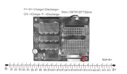
It only has 26 balance leads (the full board is populated) for a 26s bms, and looks like it takes the first negative from the main B- port. Then the balance leads all go to the +ve side of the cells, but there's one more set of pads on the bottom right that I haven't figured out yet. Traces underneath (I'll get a picture later) look like it connects to the 26th cells +ve, so is this maybe the pack +ve or charge +ve or perhaps not even needed as the 26th cell +ve is connected?

Any advice my gurus of electrons?
 
Here are the pictures of the back of the board:
IMG-20121106-00007.jpg


That trace goes to the pins which lift to the top of the board. The labels next to the pin can be seen in the next picture. From top to bottom they say R15, R13, B+ and B+:
IMG-20121106-00008.jpg


Sorry, for some reason I didnt get good focus on my phone.
 
if you are asking if it is ok to skip the last and top most sense wire since it has a connection on the board already from the positive terminal of the battery then the answer is no.

you want all the sense wires to be identical and having the sense wire on top of #26 means it has to be connected in the same way as all the other sense wires.
 
Thanks guys, not asking if I can skip the top sense wire, trying to figure out what the big connector is on the bottom right when looking right way up, or top right when looking at the bottom of the board. My guess is it's a battery + for charging, but I'm really not sure.

The only wiring diagram I got is this: http://i174.photobucket.com/albums/w112/pgpatrick/diagram.jpg

But nowhere n the board is there a P+ or a pad with B+, that's why I think it's the last two pads on the bottom right. The other thing is that there are only 26 balance leads for a 26s BMS, so obviously one lead is coming from either B- or B+.
 
I believe I ordered the same BMS from here:
http://www.linergy-shop.de/product_info.php?info=p759_bms-60a-24s-lifepo4----nr--470---.html

I didn't have a chance to take a look for it yet. Linergy is rating it to be 24s and the number 470 is matching.

Maybe these topics could help somehow:
http://www.linergy-forum.de/viewforum.php?f=7&sid=d4682882315b5fb104adfc9825ccad74
 
the B- lead is how the bottom of cell #1 is connected to the BMS. so through the big black wire. all the others go on top of #1-26.

these BMSs bring the B+ back onto the BMS to power the LVC and HVC circuits. the signal lines from each channel's LVC or the HVC signal go to some transistors at the bottom of the pack that control the output mosfets.

there is a zener diode to control the voltage these transistors see and the signal line turns off these transistors that drive the gates of the output mosfets. mosta that stuff is under the goop.
 
dnmun said:
the B- lead is how the bottom of cell #1 is connected to the BMS. so through the big black wire. all the others go on top of #1-26.

these BMSs bring the B+ back onto the BMS to power the LVC and HVC circuits. the signal lines from each channel's LVC or the HVC signal go to some transistors at the bottom of the pack that control the output mosfets.

there is a zener diode to control the voltage these transistors see and the signal line turns off these transistors that drive the gates of the output mosfets. mosta that stuff is under the goop.

Thanks dnmun, so am I right in thinking that the two pads on the bottom right (circled in red) of the wiring diagram is for B+ then?
 

Attachments

  • 26sBMS.jpg
    26sBMS.jpg
    104.8 KB · Views: 634
yes, some of the BMSs bring the B+ back onto the BMS in order to drive the circuits for the LVC and the HVC.

the positive power to the controller P+ is usually attached at the same point, but it can actually be connected directly to the battery at another spot. if you connect the controller directly to the battery and not to this spot on the BMS, then the wire running from the battery positive to that B+ spot can be tiny because it only carries a small current. tiny as in 26 gauge.


ping uses just the lower 4 cells to make enuff voltage for the mosfet gate drives. these types of BMS use a zener diode to break the voltage down enuff to use the pack voltage to drive the transistors in the LVC and HVC circuits.

for charging the charger negative is connected to P- and the charger positive goes directly to the positive terminal of the pack.
 
Back
Top