Help with proportional regen and speedo setup on Cycle Analyst V3

hieronymus

10 mW
Joined
Mar 20, 2021
Messages
21
[EDIT] Summary: the Grinfineon controller is in sensored mode, but there is no poles signal at the CA, so there seems to be a problem with getting the Halls signal from the controller to the CA.

Just getting my DIY e-scooter set up and running into two issues, perhaps related:
  • the speedo shows zero when the motor is spinning
    proportional regen isn't working--the wheel gradually slows to a halt and Watts remain in the positive zone

I have:
  • CA V3
    T-Clever thumb throttle, connected to the CA
    Grinfineon C4825-L10
    this motor: https://www.alibaba.com/product-detail/60v-48v-13-inch-800w-electric_62382170783.html

Notes:
  • the LED on the controller is a steady red, indicating sensored mode
    when spinning the motor using the throttle, and when manually rotating the rear wheel, there is no movement in the arrow beside the 'P' on the speedo setup screen

Some settings:
  • Spd-Circumf 1037 mm
    Spd-Poles 23 [note: I don't know how many poles are in this motor and I can't count them since there is no signal when rotating the wheel in the speedo setup screen. Just out of curiosity, I tried setting the number of poles to 8, 12, 16, 20, and 26, but there was no change]
    Throttle Output-MinOut 1.0 V
    Throttle Output-MaxOut 3.6 V
    Ebrake-Signal Lvl-Low
    Ebrake-PropRegen-Enabled
    ebrake-BrakeOut 0.8 V

I'm 100% new to all of this so don't be afraid to point out the basics. Thanks for any help
 
hieronymus said:
the speedo shows zero when the motor is spinning
Does it show a speed when the motor is not spinning? (this may sound like a dumb question...but if it does it could indicate certain problems in wiring)
What are you using for a speed sensor? Are you using the external speed sensor (looks like a black stick), or are you using the hall sensor wire from the controller/motor (via the CA-DP plug on the controller)? Or something else?
This:
when spinning the motor using the throttle, and when manually rotating the rear wheel, there is no movement in the arrow beside the 'P' on the speedo setup screen
indicates no valid signal is connected to the CA's speedo input wire, or that the wire/connection is broken somewhere between the speed signal output and the CA's PCB input for that signal.


proportional regen isn't working--the wheel gradually slows to a halt and Watts remain in the positive zone
IIRC, you have to be using hall sensors to the controller to get proportional regen to work. This appears to be working since you get the steady red LED on the controller.

If the CA doesn't detect a speed, it may think you are already stopped and so not apply any braking. I've never tried this scenario, but I suppose it is a reasonable operational method for the programmer to have assumed, so it's possible.


Which firmware version of the CAv3 do you have? It lists this on it's startup screen. Some versions are slightly different in behavior or menus, so knowing which one it is may help troubleshoot. Also, which specific hardware version do you have? CA-DP, CA-SA, etc? (this isn't marked on it, but it is on the page you purchased from if it came from Grin Tech). And which connectors does your system use--the new waterproof ones, or the old JST style?


Just to be sure, have you gone thru *all* of the menus, in order, from the manual (or the Grin Videos or setup menu explanations on this page
https://ebikes.ca/product-info/grin-products/cycle-analyst-3.html ), and setup all of them to the correct settings for your system? Various settings in different menus do interact, and differently in different modes of operation, so if you haven't set up the whole CA yet it's possible some things wont' operate as expected. BTW, if you don't already have it, the USB-serial cable and the CA setup program are very handy, in being able to set it all up right there on the computer screen, instead of one menu at a time on the CA itself. You can also create multiple setup files with different ways of operating, and uplaod them to the CA whenever you need to from the computer, to experiment until the system works as desired, or to use the system for different purposes.

The first step, though, is to be sure it is all wired up correctly, and it does sound like the speed sensor is not.

What is the complete wiring setup you have on the system?
 
Thanks amberwolf for the detailed reply! Some more details:

  • The speedo also shows zero when the motor is not spinning
  • I'm using the hall sensor from the motor as a speed sensor
  • I have the Cycle Analyst V3 Direct Plug Cycle Analyst with Waterproof 8 Pin HiGo CA Plug for Ready-to-Roll Kits https://ebikes.ca/shop/electric-bicycle-parts/cycle-analysts/ca3-wp-and-mfswitch.html
  • Firmware version 3.14

Wiring setup:
  • T-Clever thumb throttle: connected to CA
  • CA: connected to Grinfineon C4825-L10
  • motor (48V version of https://www.alibaba.com/product-detail/60v-48v-13-inch-800w-electric_62382170783.html ): connected to Grinfineon C4825-L10
  • battery pack (36V LiGo batteries): connected to Grinfineon C4825-L10
I've gone through the various menus and I don't see any other settings that seem like they would have an effect on the speed and regen issues (and yes, the setup utility software is handy for sure).

Any other recommendations at this point? Thanks
 
As the controller LED is a solid red, and the motor runs smoothly, I assume that means that the Hall signals are getting through between the motor and the controller.

But as there is no movement in the arrow beside the 'P' on the speedo setup screen, I assume that means that the Hall signals are not getting through to the CA. (These are my novice assumptions...)

Is the analysis I just gave correct? And if so, what could interfere with the Hall signals getting through to the CA? And if not, what else could be the problem here?

(I disconnected and re-connected everything again (throttle to CA, CA to controller, controller to motor) so I don't think the problem would be in the connections.)
 
One more thought: a key question is whether the continuous red LED on the controller definitely indicates that the Hall signals are getting through between the motor and the controller. If so, then the problem is not in the connection between the motor and controller; but if it is possible for the LED to falsely indicate that the controller is in sensored mode, then there's a chance there could be a problem with the Hall wires, for example.

So: does the solid red light definitely indicate that the Hall signals are getting through between the motor and controller?
 
hieronymus said:
As the controller LED is a solid red, and the motor runs smoothly, I assume that means that the Hall signals are getting through between the motor and the controller.
Yes.

But as there is no movement in the arrow beside the 'P' on the speedo setup screen, I assume that means that the Hall signals are not getting through to the CA. (These are my novice assumptions...)

Is the analysis I just gave correct? And if so, what could interfere with the Hall signals getting through to the CA? And if not, what else could be the problem here?

Yes, that's what seems to be happening. The problem can be anywhere from inside the controller where the CA-DP connector wires are soldered to the pads on the PCB inside the controller, all the way to inside the CA where the wires are soldered to the pads on the CA's PCB.

The CA is easy to open, just four philips screws, so that is the first thing I'd open up if I were doing that. Then I'd verify there is a wire soldered to the SP pad on the CA board edge, and measure wiht a voltmeter set to 20VDC, red probe on that pad, black probe on battery negative. Spin wheel. If no signal occurs, the problem is before this point (which is good, because it means teh CA isn't actually broken, and it's probably just a wire, which is easier to fix).


(I disconnected and re-connected everything again (throttle to CA, CA to controller, controller to motor) so I don't think the problem would be in the connections.)
It can still be in the connector contacts, for instance if a barrel in the female plug is spread open just enough to not make contact with the pin in the male side. Or it can be that the contact isn't actually connected to the wire that goes to it (not soldered, or crimped). You can't really check either of those. But another thing that can happen is the thin little pins in these Higos can be bent over flat, and not even go into the female barrel contact, and *that* you *can* see.
 
hieronymus said:
One more thought: a key question is whether the continuous red LED on the controller definitely indicates that the Hall signals are getting through between the motor and the controller. If so, then the problem is not in the connection between the motor and controller; but if it is possible for the LED to falsely indicate that the controller is in sensored mode, then there's a chance there could be a problem with the Hall wires, for example.

So: does the solid red light definitely indicate that the Hall signals are getting through between the motor and controller?
It means that the controller is receiving valid hall signals and is running in sensored (sinewave) mode.

If the motor sounds noisy rather than silent, then it may be running in trapezoidal mode, which also means that it is not getting valid hall signals.

This controller does have a fallback mode where it will still work with only two hall signals--but it may start rough rather than smoothly in some wheel positions. If the sensor that isn't working happens to also be the one the CA is trying to read for speed, then that would also explain the other issue(s).

The Grinfineon manual explains this probably better than I do. :oops:

Since you have the overmolded waterproof motor connectors it is harder to test the halls, as there are no points to probe without cutting into cables, or opening up the controller. Doing the latter is your best first option, to test the hall signals at the actual pads on the controller PCB. Usually marked as Halls 5v U V W GND, where UVW are the three signal. (the phases are usually marked as A B C)
 
Thanks for the additional feedback, very helpful.

Another observation that backs up the idea that the controller is in sine mode: the motor starts smoothly from any wheel position.

I'll hold off for the moment before opening up the CA or anything else as regen and speedo isn't super critical for right now. But sounds like that will be the place to start. I'll update with progress (hopefully...)
 
Ok, another detail that may be relevant... I had spliced the cable coming from the motor to the cable that connects to the controller. I had thought it was irrelevant since the controller is running in sensored mode which would mean that the connection between motor and controller is fine. But perhaps it's more complicated than that?

Looking at the descriptions of the various connections that are printed on the controller, I see that the description of Motor Plug (L1019) is:
Y,G,B=motor phases
y,g,b,r,bk=Hall signals and 5V
w=Speed Sensor
p=NTC

Could the white "Speed Sensor" wire be the issue?

In my setup, the cable coming out of the motor only has phase wires and Hall wires; there are no other wires (white or otherwise). I spliced those wires to the appropriate wires in a cable that ends in an L1019 connector to connect with the controller https://ebikes.ca/shop/electric-bicycle-parts/wiring/l1019-m.html .

When splicing, I noticed that in addition to the phase wires and Hall wires, the L1019 cable contains a white wire, a grey wire, and a bare wire (which is inside a foil sheath that contains the y,g,b Hall wires).

The grey wire is for a thermistor; the white is for speed. Since there are no wires on the motor end to connect to those, I left them disconnected (and insulated).

I have no idea what the purpose of the bare wire in the foil sheath is. I also left that wire disconnected (but put some insulation on the end).

So that makes two new questions:

1. Could the white "Speed Sensor" wire in the L1019 cable be the issue? If so, how could it be resolved?
2. Could the bare wire in the L1019 cable be the issue?
 
hieronymus said:
Could the white "Speed Sensor" wire be the issue?

In my setup, the cable coming out of the motor only has phase wires and Hall wires; there are no other wires (white or otherwise). I spliced those wires to the appropriate wires in a cable that ends in an L1019 connector to connect with the controller https://ebikes.ca/shop/electric-bicycle-parts/wiring/l1019-m.html .

When splicing, I noticed that in addition to the phase wires and Hall wires, the L1019 cable contains a white wire, a grey wire, and a bare wire (which is inside a foil sheath that contains the y,g,b Hall wires).

The grey wire is for a thermistor; the white is for speed. Since there are no wires on the motor end to connect to those, I left them disconnected (and insulated).
If the controller is internally wired to send that speed sensor signal to the CA-DP connector, then that is why there is no speed signal to the CA.

If the controller is internally wired to send one of the hall signals to the CA-DP connector, then there's something else interfering with the signal from that point to the CA's PCB.

If the former is the case, then you can alter it to be the latter (see end of post, first), and then it should all work. It doesn't matter which hall signal is used for the speed signal.


I have no idea what the purpose of the bare wire in the foil sheath is.
It's a "shield ground" wire--it connects that foil sheath electrically to whichever ground you have available (battery negative, typically, or the hall ground, whichever is available at that end of things). If that shield is around the signal wires only, and separates them from the phase wires, then you can use that shield ground to battery negative to help eliminate glitching if you run into that problem, where electrical noise on the phase wires under high loads / high current causes noise on the signal lines causing operational problems. If the bare wire is already connected to ground at the controller end, then you don't need to connect it to anything at the motor end. (you can simply measure using continuity or 2ohm setting on a meter from the motor end of the bare wire to battery negative on the controller to verify if it's already connected).

But this wire wouldn't be the issue. EVen if it's not connected it won't cause a problem of no signal, it would tend to cause a problem with excessive signal (jumpy too-high speed readings, incorrect motor operation).


The good news is that if your splices are accessible, you can direclty test the hall signal wires to the CA speedo wire, if it is all connected (except the battery). Meter on continuity or 2ohm setting, then red lead on the CA speedo pad on the PCB (assuming you can't measure at the connector with it all plugged in due to the molded plugs), then black lead on each of the three hall signal wires at the splices, each in turn, and then if there is no connection (OL on meter) then try the white speed wire on the cable, and if you get a reading on that one, then you may be able to just connect that white wire to one of the hall signal wires, and it'll now read that hall as the speed signal.
 
Great info. I'm going to start by looking into the question of whether the controller is internally wired to send the white wire speed signal to the CA-DP connector and go from there. Thanks!
 
The word from Grin is that the Grinfineon is both internally wired to send the white wire speed signal to the CA for the speedo, AND it's internally wired to send a Hall signal to the CA for the speedo. They say "It depends on the motor. The controller only relays the speed signal to the CA."

In that case, if I understand correctly, the problem isn't related to the white wire, nor any of the Hall wires, as the Hall signals are getting through between the motor and controller (according to the steady controller LED and the fact that the motor starts smoothly from any position). So that narrows down the problem again to somewhere between the controller and the CA. So that area would be the best place to focus my efforts, is that correct?
 
hieronymus said:
The word from Grin is that the Grinfineon is both internally wired to send the white wire speed signal to the CA for the speedo, AND it's internally wired to send a Hall signal to the CA for the speedo. They say "It depends on the motor. The controller only relays the speed signal to the CA."

In that case, if I understand correctly, the problem isn't related to the white wire, nor any of the Hall wires, as the Hall signals are getting through between the motor and controller (according to the steady controller LED and the fact that the motor starts smoothly from any position). So that narrows down the problem again to somewhere between the controller and the CA. So that area would be the best place to focus my efforts, is that correct?

If it already has the two wires tied together like that, then the problem "can't" ;) be between controller and motor based on present behavior.

So, yes, it would then have to be between controller and CA.


There is, however, a potential problem with what Grin says about that wiring in the controller. (potential, because I'm sure they know more about their controllers than I do, but they dont' have this info on their site with wiring details, so I can't verify how it works).

If the controller is internally wired so that it directly ties the speedo signal wire from the motor connector to one of the hall signals, then it can't be used with a number of geared hubmotors (like some Bafangs, etc) which have both halls *and* a separate speedo signal, because doing so would cause the controller to attempt to operate with that merged speedo/hall signal, which could cause (probably would cause) undesired operation due to invalid hall signal states / motor position info. Even the GMAC couldn't be used with it, as it also has this separate speedo sensor (and AFAIK regular hall sensors).

So, I don't see how that could be wired for both, without some extra electronics in there (however simple) to prevent feedback of the speedo signal into the controller's hall sensor input.

I looked for but cant' find info on Grin's site about this on the controller itself. The manual they have doesn't cover the new connector style, only the old JST/Anderson setup, and it says (regarding sensorless operation, so that no hall sensors would be connected to the controller) "When using a Cycle Analyst, you won't have the option of picking up thespeed signal from the motor hall line and will require an external speedo sensor and spoke magnet (i.e. CA-DPS or CA3-DPS)" which means that the newer controller wiring is definitely different than the old version (like what I have here), and the controller itself may be different electronically, as well (don't know). That statement precludes the ability of the controller to pass thru the speedo signal because the old wiring didnt' have a connector pin for that speedo signal (whereas the new connector does).


So...if it does indeed use electronics (diodes or something more complicated) to combine the signals to the CA, then it's possible there is something wrong with the electronics that allow the hall signal to pass to the CA. (reversed diode, etc).

It could be something as simple as a broken wire.
 
Thanks for the in-depth analysis! (It'll take me a while to absorb...)

Got around to one of your first recommendations:

The CA is easy to open, just four philips screws, so that is the first thing I'd open up if I were doing that. Then I'd verify there is a wire soldered to the SP pad on the CA board edge, and measure wiht a voltmeter set to 20VDC, red probe on that pad, black probe on battery negative. Spin wheel. If no signal occurs, the problem is before this point (which is good, because it means teh CA isn't actually broken, and it's probably just a wire, which is easier to fix).

When spinning the wheel, I got a signal, about 5V. I assume this means there's a defect in the CA?
 
hieronymus said:
When spinning the wheel, I got a signal, about 5V. I assume this means there's a defect in the CA?
If this is a signal that toggles from around 0V to around 5v (may be 1v-4v) about 23 times per wheel revolution (number varies depending on number of magnets in the motor for any DD (non-geared) hubmotor), then that means the signal is indeed getting from the hall sensor in the motor all the way to the point you measured at.

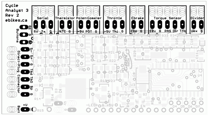
If that is the SP pad on the short edge of the CA board here
https://ebikes.ca/pub/media/wysiwyg/CA_Pad_Layout.gif
CA_Pad_Layout.gif

then there is something going on in the CA causing it to not see the speed signal. I don't know of any setting that could prevent it from at least *seeing* a signal was happening, so it probably would mean a hardware issue. It wouldnt' be a broken wire or bad solder joint at the SP wire, or else the signal couldn't reach the pad. But it could be anywhere between that pad and the CA's MCU chip, and while it might be fixable, if this is a new CA from Grin Tech, it should be under their warranty. I'd recommend asking them directly if they can think of anything else it could be (you can reference this post and yours just above, or even the whole thread, if it helps convey what's already been checked and thought of, just in case we've missed something here).


All the speedo related settings I know of are here:
https://ebikes.ca/product-info/grin-products/cycle-analyst-3.html#SetupSpeedo
The #poles setting just controls how many toggles of the input it takes to count as one rotation of the wheel. Then that is multiplied by the Circumf setting to determine distance travelled. I don't know how either of those could cause no signal to be detected, so that leaves hardware, AFAICT.

For completeness, this is the Explanation of Speedometer Settings from that page:
The CA displays vehicle speed whenever there are pulses coming into the Spd input from either a motor hall signal (CA-DP device) or a spoke magnet and sensor (CA-DPS device). Wheel size and poles settings must be correct for an accurate speed display.

[ Spd->Units ]
Select to use units of kilometers or miles. Changing this setting will not rescale existing distance-related values such as odometer, speed limits etc.

[ Spd->Circumf ]
Exact wheel circumference in mm. The table below shows typical values for common tire sizes. A more accurate value can had by placing a dot of paint on the tire, riding forward one or more tire rotations, and measuring the distance on the road between dots.
Tire Size Circumf (mm) Tire Size Circumf (mm) Tire Size Circumf (mm)
16 x 1.50 1185 24 x 2.125 1965 26 x 2.25 2115
16 x 1-3/8 1282 26 x 1-1/8 1970 26 x 2.35 2131
20 x 1.75 1515 26 x 1-3/8 2068 700c x 23 2097
20 x 1-3/8 1615 26 x1-1/2 2100 700c x 28 2136
24 x 1-1/4 1905 26 x 1.5 1995 700c x 32 2155
24 x 1.75 1890 26 x 1.75 2035 700c x 38 2180
24 x 2.00 1925 26 x 2.0 2075 700c x 2.0 2273

[ Spd->#Poles ]
The number of pulses on the Spd input that is considered one full wheel revolution. For direct drive (DD) hub motors using a CA-DP device, pole count is the number of magnet pole pairs in the hub (usually between 8 to 26). Geared motors with an internal speed sensor typically have 6 pulses per revolution and can also use a CA-DP device.

Mid-drive motors or geared motors without an internal speed sensor require a CA-DPS device with external speed sensor. The pole count is the number of magnets on the wheel (usually 1). Additional wheel magnets can be added for better low speed control.

The table below gives values for common DD motors. The number of poles can be determined by rotating the wheel slowly one complete revolution. The pole count is the number of times the arrow next to 'P' on the SETUP SPDOMETER screen flips DOWN then UP.
Motor Family # Poles
Crystalyte 400, Wilderness Energy 8
Crystalyte 5300, 5400 12
TDCM IGH 16
Crysatlyte NSM, SAW 20
Crystalyte H, Crown, Nine Continent, MXUS,
and most generic 205mm DD motors 23
Magic Pie 3 and other 273mm DD Motors
 
It's actually a steady signal of about 5V, no variation as the wheel spins. So what would that signify?

[Dumb question: should the CA be switched on during this test? (I assumed yes. No signal visible when the CA is off, which makes sense to me.)]

Thanks for that graphic of the CA board, that's helpful. And thanks as always for your help.
 
hieronymus said:
It's actually a steady signal of about 5V, no variation as the wheel spins. So what would that signify?
That means there is no speed signal reaching the CA's SP pad. That pad has, AFAICR, an internal pullup to the CA's 5v.

Motor hall sensors (both position and speedo) work by grounding a 5v signal on a "pullup" resistor that's inside the controller; having an extra on the CA doesn't hurt anything. In the CA, when this signal goes to ground (around 0-1v), the CA reads it as a speedo pulse.

The other type of speed sensor the CA uses is a magnetic reed switch that mounts on the frame or fork, looks like a black stick, and a magnet on a spoke of a wheel (or glued to the outside of a hubmotor sidecover, etc). This type is wired from ground to the SP pad, and every time the magnet passes it, it grounds that "pulled up" 5v, and the CA then reads it as a wheel revolution (assuming #poles = 1 and there's just one magnet--I use three magnets and #poles = 3 for a slightly quicker speed update at lower speeds).


So it does mean there is some form of connection problem somewhere between that pad and the connection inside the controller where the hall sensor signal is connected to the CA wiring.

The simplest way to troubleshoot where that is, given the waterproof connectors, is to first measure from the CA SP pin since you have it open already, to the connector on the cable from the CA that goes to the controller from that point. The pin on that connector to test is the second one from the "end" of the curve. Whcih end depends on which connector you're testing. On the CA end (the first one to check) it's the second from the "righthand" end of the curve, if you are holding the connector with the pins sticking out toward you and the gap in the pins pointing down.
https://ebikes.ca/pub/media/wysiwyg/CA/WP8-Pinout.jpg
WP8-Pinout.jpg

To test this, set the meter to 2ohms, or continuity, and put the black lead on the SP pad of the CA board, and the red lead on that connector pin. If it's broken, you get OL on the screen, and no sound. If it's good, you get a very low reading for ohms, and a continous beep for continuity. Since the CA is disconnected at this point, there's no power to worry about (it gets power from this connector), but it'd be good practice to have disconnected the battery first anyway. ;)


If that cable tests ok, then the problem would probably be in the cable from the controller to the CA, it's connector, or inside the controller where the cable is wired to the board.

But...before you open the controller up to test it's wiring (as this is more complicated than opening the CA, with more risk of damage), you can still do the hall test on your wire splices to the controller from the motor, which I don't think has been done yet. It *should* be safe to assume they all work because the controller is in sensored mode, sinewave is working, and it's smooth operation. But, we all know what "assume" stands for, right? ;) :lol:
 
Ok! Looks like I know what the next step to take is, thanks.

(And after my last post, I realized it was misleading, as the 5V reading was constant, doesn't matter the position of the wheel or if it's spinning.)

Will update with progress (one hopes). Thanks
 
Checked for continuity between:
- SP pad on CA and
- connector pin on cable that connects to controller.
Continuity is OK.

Checked for continuity between:
- SP pad on CA and
- all 3 Hall signal wires on motor cable that connects to controller
No continuity.

Checked for continuity between:
- SP pad on CA and
- white speed wire on motor cable that connects to controller
No continuity.

So, it's looking like the problem is probably in the controller itself?
 
hieronymus said:
Checked for continuity between:
- SP pad on CA and
- connector pin on cable that connects to controller.
Continuity is OK.
So the CA is good all the way to the connector to the controller.

Checked for continuity between:
- SP pad on CA and
- all 3 Hall signal wires on motor cable that connects to controller
No continuity.

Checked for continuity between:
- SP pad on CA and
- white speed wire on motor cable that connects to controller
No continuity.

So, it's looking like the problem is probably in the controller itself?
Or the cabling from it to the CA, or the cabling from it to the motor.
Before opening up the controller, test the actual hall signals at the motor cable splice points (the only accessible place to do so wihtout opening the controller or cutting into cables). If any of them does not toggle from around 0v-1v to around 4v-5v as the wheel is rotated by hand, then that one is not getting a signal to the splice point. Meauwure with meter on 20VDC and black lead on battery negative and red lead on each signal in turn.

As long as all three signals toggle as expected, then it means something is probably wrong in the controller wiring itself.

Just for giggles, if they do all work, connect the speedo wire of that motor cable to any one of the hall signal wires (doesn't matter which), leaving it still connected to the hall wires of the controller, then spin the wheel and see if the CA sees a signal. If it does, it means that the speedo wire of the CA is wired only to that inside the controller, and not to one of the halls. If this is the case, you can then simply make that connection permanent, so one hall feeds both speedo wire and hall signal wire, and then at least this part is resolved. (or you can open the controller and fix the wiring, or send it back to Grin to fix, etc).

Then we can work on the regen thing. :)
 
Progress! Poles are detected at the CA after connecting the white speed wire of the controller's motor cable to a Hall wire in the cable coming from the motor.

Other observations:
- when Hall wires are disconnected, the LED on the controller blinks, and the motor seems to start a bit less smoothly in some positions (so at least the steady LED doesn't seem to be lying)
- all Hall wires show a voltage varying from 0 to 5 V when turning the wheel by hand
- there are 15 motor poles, fwiw

But still no regen. Any recommendations on next steps?

Thanks!
 
Ok. The regen problme is this, right:
proportional regen isn't working--the wheel gradually slows to a halt and Watts remain in the positive zone

So, first, do you have the brake lever and/or throttle wired only to the CA, or also to the controller? They should only be wired to the CA for this.

If they're wired to the CA only, then, wiht the powered wheel off the ground:

--On the main screen of the CA, does the little brake lever icon move to show the brake is pulled, when it is?

--when you look at the "first screen to the left" on the CA (one press of the left button on it's front panel, when at the main screen), what are the throttle in and out values you see when the wheel is moving, with the throttle at say, 1/4 of it's travel?

--when you pull the brake lever, what are the throttle in and out values you see?

--when you pull the brake lever, *and* then move the throttle from off to max travel, what are the throttle in and out values you see?
 
That's right, that was the regen problem... but it's working now.

After the steps described in my last post, the ebrake regen started working; no CA settings were changed.

The proportional regen started working after I changed a key setting: Throttle Min Out is now 0.0 V.

Other settings:
Throttle Input Zero Threshold 1.00 V
Throttle Input Full Threshold 4.10 V
Throttle Input Fault Threshold 4.60 V
Throttle Output Min Out 0.00 V
Throttle Output Max Out 3.80 V
Ebrake Brake Out 0.90 V

(If anything looks odd about those settings, let me know...)

Thanks, amberwolf, for the detailed and very informative posts! The solution turned out to be quite straightforward: connecting the white speed wire to a Hall wire, and changing the Throttle Min Out. But it sure wasn't obvious to me at the outset, so thank you.

[Additional details for anyone who consults this thread for their own troubleshooting purposes:
- the ebrake and throttle are wired to CA
- the brake lever icon moves when the lever is pulled (and did so before my first post in this thread)
- throttle in and out values when the wheel is moving with the throttle at around 1/4 of its travel: 1.6V, 0.7V (note that these were observed after changing the Throttle Min Out as mentioned above (and tweaking some other settings))
- throttle in and out values when brake lever is pulled and throttle is then moved from off to max travel: 4.25V, 0.00V
 
hieronymus said:
After the steps described in my last post, the ebrake regen started working; no CA settings were changed.

The proportional regen started working after I changed a key setting: Throttle Min Out is now 0.0 V.
Throttle Min Out *IS* a CA setting.... ;)

And you also say you "tweaked some other settings", which means that CA settings were *definitely* changed. :/ I point this out because accurate info from those being helped is necessary for accurate input from those helping. ;)


But AFAIK you shouldn't need to change that setting. What that does is when the throttle input is at it's lowest, it then outputs that minimum output voltage. So when you are riding and let go of the throttle, or move it to it's lowest setting, the bike will begin braking to maximum braking. The same thing will also be true if one of the limiting modes engages in a way that brings throttle to minimum, and so the bike could unexpectedly brake.

EDIT: If you don't use any of the limiting stuff (speed, power, current, etc) so that the throttle will never be rolled back by it, potentially to below 0.8v initiating braking, you could build a detent into your throttle at the point just before the 0.8v output point on the CA throttle out screen, so that when you let go of it it never goes below that. But if you deliberately push it past that point, then you control the braking power. I don't know how easy it would be to control like this, as I never thought of doing this until now, but it is a potential way to make a regular throttle work a little bit like a Vectrix throttle. (would be more like it if you added a spring return to force the throttle back to the >0.8v mark when released from braking).


For the Grinfineon, max regen is at 0v throttle (min is 0.8v and above that is no braking).

Normally the Throttle Min Out is around 1v (so that it is just (say, 0.2v) below whatever the minimum voltage that is required to start the controller making the motor do something).


Ebrake Brake Out 0.90 V
AFAICR, *this* is the one you want at 0v. I'd go check my trike's CA but Kirin (the St Bernard) is asleep on my legs.... When she wakes up I can do that, if needed.

EDIT: I looked at the grin CA v3 info page and found this:
[ EBk->Prop Regen ]
Chooser to select if proportional regen is active when ebrakes are applied.

Disabled: Throttle OUT voltage is set to Brake Out when ebrakes are applied. [Default]

Enabled: Throttle OUT voltage is set to Brake Out when ebrakes are applied and the rider throttle is ZERO. As the rider throttle is increased with ebrakes applied, the Throttle OUT voltage decreases from Brake Out to 0V to increase the proportional regen braking effect. All Grin controllers support this feature.

Which means that for your system you would set this to 0.8v if you want *full* control of prop regen, starting from min braking, or if you want to have some default level of braking as soon as you pull the lever you could set it to 0.5v so that it starts at about 30-40% of max as soon as you pull the lever, and then you use the throttle to increase braking.
 
Should have been clearer—no CA settings were changed after the first post until after I connected the white speed wire to a Hall wire; the ebrake regen started working before any setting changes.

Thanks for the further info, I'll try those settings next...
 
Back
Top