Hill Scooters' Scooter

2024-05-22 17.32.15.jpg 2024-05-22 17.33.00.jpg

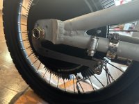
Got the back wheel setup with the Grin v7 regen torque arm; came out great. Alas, because of the way the front fork dropouts are attached to the fork, I can't use the V7 there -- simply not enough room once you add enough washers to get the TA to sit flat.

2024-05-23 12.14.31.jpg 2024-05-23 12.14.39.jpg

I do have a v6 which worked, and just because why not, I dug one of those cheapo versions out of my parts bucket to help out on the front motor.

I may shop around for a 150mm front fork as having the torque arm on the "inside" seems to work pretty well, though might not be enough axle on the outside then.
 
BOOM!

2024-05-24 16.15.31.jpg

2024-05-24 16.16.30.jpg

Printed a larger controller box and got that fitted on. Got a bunch of the wiring right-sized (made some of the phase extensions way too long) and got it all nicely wrapped up in some sleeving. Replaced the front tube (pinched in on first install, doh!). Just generally buttoned up most stuff and got it out for a test ride.

Touch the throttle and you're at top sped. I did de-rate the front motor a bit due to the less-than-awesome torque arms, which was probably a good call since even taken down to about 80% of the rear's config, it still did a liiiiitle bit of chatter on take off.

No hill could stop this thing -- the battery hasn't been charged for a while, so it was in the very low voltage range and only holding 20-22mph, but it did that up every hill in this area and there are some[1] doozies[2].

There are still a few finishing touches to sort out, like fixing up the left-hand-front-brake which is on the right side, just upside down (on the left, I have a brake lever that's actually a hall trigger, basically, which controls progressive regen). For the heck of it, I may toy with de-powering the front motor down to 10A just to see how strong it would be as a single motor. I want to get some heat-shrink wraps around those nylon sleeves to tidy up the ends. I may toy with some field weakening to see if I can eek this into the 35mph range.
 
I'd like to see some footage of this thing climbing monster hills.
I did 50mph up a 4% grade on a single motor in a 26" wheel, you have about 2.5x the torque potential i had.

I bet those motors both run cool up steep grades and you get great efficiency on hills.
 
14mm on both sides -- different sizes on the two sides is....really weird, honestly.
It's the cassette. When you have to fit the axle through a skinny mechanism originally designed for pedal bicycles with 10mm quick release axles, well, you get dumb stuff.

I worked on a Super 73 today that had a useless cassette freehub (that had only one speed), 12mm right side axle and 14mm left side axle. And the dropouts (and rear brake, and rear fender) had to be detached from the frame to remove the wheel. It made me want to horsewhip both the product designer and the nincompoop who bought that crap.
 
I'd like to see some footage of this thing climbing monster hills.
I did 50mph up a 4% grade on a single motor in a 26" wheel, you have about 2.5x the torque potential i had.

I bet those motors both run cool up steep grades and you get great efficiency on hills.
Good news, since I have the Megan hooked up, I get complete, full, GPS linked data logging!

And, yeah, I don't think I even saw the motor temps move at all. Checking the log, the "worst", brief, spikes happened during the regen going down the 16% segment (65C), lol. Otherwise, it kept pretty much steady at 30C.

I'll post a more data logged run when I can segment it out a bit more. And with a charged battery :)
 
Absolutely excellent sir. I can’t help but smile just thinking how much fun I would have on your toy brother. I am a full blown 2wd nut so I am just started building a new monster scooter with 26” wheels and 48v 500w motors for all round use. Yours must be extra torquey and zippy with your 20” wheels. I also am hoping you will spoil us with some footage of how much fun you’re having on it and the real performance. I bet few can keep up with with you off the line with anywhere near the same size batteries. I also feel more stable with the extra weight of the hub motors, once you get used to it and adjust. i would like to hear how it feels for you, because on my giant scoot, with big heavy hub motors, the one drawback I have found is the extra weight in the front wheel really gives it a truck like feel on very rough roads. I feel this is probably just because my wheels are so extremely heavy, each one about as much as your scoot!, and my suspension is very stiff. Anyway your build looks awesome and you really got on the road quickly and efficiently. Thank you for sharing and look forward to more excellent work bro. 👍
 
Off topic: You got a build thread on that hub motor power wheels sitting in the background? I've always wanted to do a 4 wheel drive hub motor power wheels/go kart. Seems like it would be so much fun
Not on here, but over on FB I do.

tldr; two hub motors out of a hover board, big chunk of aluminum across the bottom with some fixing plates, two VESC controllers, a hall pedal and a nicer battery. Zoom zoom.

Recently the girls fried one of the motors (grass + too many amps + no temp sensor == crispy fried motor) so I upgraded to slightly larger motors -- generally the same single side direct drive setup. Needs a bigger (more amp capable) battery though, as I've had to de-tune it a lot to prevent over_voltage errors during regen braking.

Super fun project; highly recommend it. Also recommend a removable key shutoff so when it's sitting at the park the army of other kids that have zero sense of personal property don't get in and immediately ride it into traffic or tree. :D (Alternatively, since it's VESC, I have a few modes setup, including a "slow beginner" mode for the polite ones that ask)
 
Got a full charge on it and took it through the Belmont hills and up & down one of the steepest roads around here a few times. First few runs generally maxed out around 22mph while climbing.

After a few runs, I went and added 20A to each motor for field weakening, just to see how it'd perform and...yeah, it was now pulling up the hill at about 26mph, and on the flats the top speed went from 25 to 30.

Actually had the new insta360 running, but since I'm new to it, I did not realize that the "loop recording" actually means it'll only record the last N minutes, not simply record in N minute chunks and then delete the oldest one as needed. What a stupid implementation of loop recording -- contrary to how every other loop recording device works. So, no up/down the hill footage.
 
Awesome build! Curious as to what sort of heat sinking, if any, that dual controller thingy requires.
 
Very cool build. I was looking at the leaf fat/snow motors and wondered if they had more low rpm torque than standard for slow speed maneuvering on hills . If I put two in my brothers trike, he might need wheelie bars .
 
So, with this setup I need to pull some pretty big power from the pack. However, these battery cases only support the smallest of BMS, certainly nothing big enough to hangle 80+ amp draws. Yet, I don't want to give up the functionality of the BMS being able to turn off the system when a fault is found.

So I got creative...

See, the controller has this "ignite" port on it. Essentially, it has three pins: ground, battery positive, and "ignite". If the controller detects the battery voltage on the ignite pin (ie, it gets connected to the battery positive wire) then the controller will turn on. Of course, no connection == controller off.

So, the battery is built with the BMS, but the main contacts are direct to the cells. I do, however, carry the BMS P- (where you would normally connect the controller's negative) out as well.

I can use this P- wire, along with the battery positive from the "ignite" port to power up a dcdc step down, produce 12v, have that trigger a relay, and that relay then allowed battery voltage back up into the ignite wire.

Here's what this looks like (ignore the directional arrows, bug in the layout software):

2024-12-13 23_07_02-Window.png
(Diagram)

As such, if the BMS shuts off the P- line, the dcdc dies, the relay stops working, the ignite port loses battery voltage and the controller shuts off.

While this works (unless the dcdc dies, which spurred this on), it's over complicated by the extra DC step down process. The only reason that's here, is because I've had a hell of a time finding relays that work at, basically, anything less than 24v dc.

Ideally, this setup would make WAY more sense:

2024-12-13 23_07_15-Window.png
(Diagram)

And, after a LOT of searching, I had believed I'd found such an option in the ED10F5 Crydom SSR

And, when I hook it up to my voltmeter in continuity mode, it behaves as I'd expect. Run 58v across the pos/neg and I get tone. Turn it off, continuity goes away.

HOWEVER, if I connect the loadin to the battery, and I probe for voltage, on the loadout I can still read 57(ish) volts. My research has lead me to now know that (some?) SSR's are just, well, leaky. A core part of their design causes this. As such, the single relay version of this is allowing the controller to operate, even when the relay is off.

Of course, why the other setup (dcdc + relay) doesn't do this is a bit of a mystery to me. Perhaps it's leakage is much smaller and simply to little to "ignite" the controller.

--

Before I go buy a mechanical relay (which creates a true, physical path blockage); is there a simple fix to bleed off the voltage when the SSR is "off" that I could employ? My grasp of these base areas of electrical circuits is...lacking.
 
Last edited:
You could try placing a 1k resistor in series with the "Ignite" line and measure the voltage across the resistor when the SSR is off. This will give you a measurement of the current passing through the line (1v = 1mA). Most likely the current will be so low you don't need to worry about it and your meter is just very sensitive.
 
You could try placing a 1k resistor in series with the "Ignite" line

I gave that a try, but the controller continues to detect battery voltage and turn on, even when the SSR is off.

The setup:

setup.png

While on:

on-power-at-bplus.jpgon-power-relay-loadout.jpgon-power-relay-loadout-after-resistor.jpg

56.3, 56.3, 55.3; controller on

While the SSR is off:

off-power-at-bplus.jpgoff-power-at-relay-loadout.jpgoff-power-relay-loadout-after-resistor.jpg

56.2, 55.7, 54.7; controller on

------------

The resistor certainly drops the voltage, but if it's still detectable, it seems the controller can still power on.
 
Wow, that's super leaky. It must be using some of that leakage to power the circuit inside.

I made a DIY solid state relay that would probably work in that application. It uses a FDA217 gate driver and a IRFB4110 from the junk box. When it's off, it's really off and maybe a few uA of leakage. I should have a schematic of it somewhere but can't seem to find it.
 
Palm, meet face.

Directionality on the load side of an SSR matters. It's not a real, mechanical relay wherein there is a complete, physical separation of the contact. It's just electronics stopping the flow; and if you connect it in reverse, it'll push through.
 
A mechanical relay won't be too bad since the load on the contacts will be very small. Be sure to put a diode across the relay coil to catch the spike when it turns off.
 
Back
Top