
lazarus2405
10 kW
So, I've finished my first build. It's a 26" faux-Schwinn S-25 full suspension MTB with a 5304 in rear, a modded controller from Bob Mcree (4110 FETs, ~70A limit - I need to measure it, might be lower - and busses reinforced with brass bars), powered by a 84V 6Ah E-Moli pack (21s2p, 15C, LiMn, 6x Milwaukee 28V packs), and a CycleAnalyst plug-in unit. I'll be posting a build thread with pictures after Easter, when I can get back to school. Until then, I will be plotting my next projects.
So, I completed my first mod. I added a toggle to the CA case and wired it to the throttle override. On for legal/sidewalk riding. Off for E-motorbike. I also modded a power strip with Andersons for 84VDC outlets. It happily drives my various electronics' chargers (so far tested things as big as my laptop down to my mp3 player). Another easy mod done. Now it's time for more.
I'll try fechter's low-throttle response mod with a trim pot (as shown here: http://endless-sphere.com/forums/viewtopic.php?f=2&t=764&st=0&sk=t&sd=a&start=56 ) to make things a little easier. That should be a pretty simple one, too. On to real mods.
Charging:
Right now, I charge my batts using three stock Milwaukee chargers. I've left the packs completely intact for charging through their stock BMS (bypassed the BMS for discharging) and simply slide the packs onto the chargers when I get home. I live in university dorms, so I lock my bike in my bike locker and carry my battery bag to my room to charge . It takes ~50min to charge a pack from 90% DoD to full, so I have my full pack of 6 charged in about 2 hours. However, I can't opportunity charge! It's almost as if that alone makes me fail at ebiking.
So, I'd like to shrink down my charging setup to fit in my bag, so that I can leave everything connected and only have to disconnect the controller and plug into an AC outlet to charge. So, each charger has three leads: +28vdc, Gnd, and temp (won't charge if the thermistor is tripped). The BMS does all the thinking, while the charger just is a dc power supply with a red and green light. I'd like to break down the three supplies and make a harness for charging, and store it all in my bag.
So, what problems might I have to overcome? Each charger would be feeding two packs in parallel, while the packs would be connected in 3s2p? Does that circuit diagram out? Will such a setup damage anything? If so, alternatives or workarounds?
Braking and Regen
I need better brakes on the bike, and I have a big honking motor Perhaps there's a connection...
The regenerative braking literature here is really a mess. From what I can tell, I have two options:
fechter's regenerative braking using a cheap brushed controller, as seen here: http://endless-sphere.com/forums/viewtopic.php?f=2&t=583&st=0&sk=t&sd=a

or a non-regenerative resistor coil design, as seen here: http://endless-sphere.com/forums/viewtopic.php?f=2&t=583&st=0&sk=t&sd=a&start=49
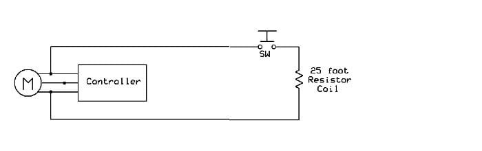
Well, I'd much rather do the former, but it's a bit more difficult. In the diagram B and M are battery and motor, respectively?
Looks like I'll take the two bridge rectifier route. The wiring looks clear enough. As for a controller, can you recommend any? Brushless, cheap as possible, able to handle 87V-77V (hot off the charger and LVC respectively), and enough amps? (In retrospect, that sounds like a very difficult request for a brushed controller. What would an alternative be?) As for how many amps is "enough", I can't find the spec pages for my batteries. Perhaps someone out there can help? Since the charger fills 3ah in 1 hour, I'd guess at the very minimum I could pump 6A into them. I don't like the sound of that, though, so a max charging rate spec would be nice. For the throttle, would it be too difficult to use a slide pot and connect it to the bike's brake lever?
Come to think of it, I'd learn more doing both. Simply take a lot of wire to use as a resistor, and a button. Can anyone recommend some good numbers for a 5404? What sort of resistance should I shoot for (as in, in Ohms), and about how much of what wire would this require? ~20' of 18AWG?
More power
Yep, I know. Such is the nature of the hobby, I suppose. I'd like to know what to start thinking about after I expand my battery pack. So, my options as I see them.
I'll get a bit more power from just expanding to 9Ah, since with 6Ah I'm getting a pretty noticeable sag at >50A. Something like 5 to 15V of sag. 50% more capacity should cut that down a bit, right?
After that, I'd want to run more amps. How high can I increase the current limit before things get hairy? 80A? Remember, these are 4110s with reinforced bus bars. I know that the FETs are rated for 180A, and I also know that because it's 3-phase, they'll be able to deliver something in the ballpark of half that. What have some of you been able to run 4110s at?
After that, I'd have to use more voltage to get more power. Since the caps and fets are rated for 100V, and since there's a 10V bootstrap, should I expect failure somewhere between 90V and 100V? Or do they have some headroom? If it was possible, I could easily add another 5 cells (labeled as "18V" packs) for a hot-off-the-charger of 108V and nominal of 104V. Is something like that dancing with death, or doable?
Then, I'd need to upgrade to 150V for more power. What would I have to replace to run at, say, 112V, 140V? Just the FETs and main capacitors? And doing so would generate a lot more heat, somewhere around 5x, I know, but I understand it is manageable. How viable is this route?
So, thanks for any help... I know it's one thread that could easily be three, but I weighed that against polluting the forum, and I'd like to keep it in one conversation. Cheers.
So, I completed my first mod. I added a toggle to the CA case and wired it to the throttle override. On for legal/sidewalk riding. Off for E-motorbike. I also modded a power strip with Andersons for 84VDC outlets. It happily drives my various electronics' chargers (so far tested things as big as my laptop down to my mp3 player). Another easy mod done. Now it's time for more.
I'll try fechter's low-throttle response mod with a trim pot (as shown here: http://endless-sphere.com/forums/viewtopic.php?f=2&t=764&st=0&sk=t&sd=a&start=56 ) to make things a little easier. That should be a pretty simple one, too. On to real mods.
Charging:
Right now, I charge my batts using three stock Milwaukee chargers. I've left the packs completely intact for charging through their stock BMS (bypassed the BMS for discharging) and simply slide the packs onto the chargers when I get home. I live in university dorms, so I lock my bike in my bike locker and carry my battery bag to my room to charge . It takes ~50min to charge a pack from 90% DoD to full, so I have my full pack of 6 charged in about 2 hours. However, I can't opportunity charge! It's almost as if that alone makes me fail at ebiking.
So, I'd like to shrink down my charging setup to fit in my bag, so that I can leave everything connected and only have to disconnect the controller and plug into an AC outlet to charge. So, each charger has three leads: +28vdc, Gnd, and temp (won't charge if the thermistor is tripped). The BMS does all the thinking, while the charger just is a dc power supply with a red and green light. I'd like to break down the three supplies and make a harness for charging, and store it all in my bag.
So, what problems might I have to overcome? Each charger would be feeding two packs in parallel, while the packs would be connected in 3s2p? Does that circuit diagram out? Will such a setup damage anything? If so, alternatives or workarounds?
Braking and Regen
I need better brakes on the bike, and I have a big honking motor Perhaps there's a connection...
The regenerative braking literature here is really a mess. From what I can tell, I have two options:
fechter's regenerative braking using a cheap brushed controller, as seen here: http://endless-sphere.com/forums/viewtopic.php?f=2&t=583&st=0&sk=t&sd=a
or a non-regenerative resistor coil design, as seen here: http://endless-sphere.com/forums/viewtopic.php?f=2&t=583&st=0&sk=t&sd=a&start=49
Well, I'd much rather do the former, but it's a bit more difficult. In the diagram B and M are battery and motor, respectively?
Looks like I'll take the two bridge rectifier route. The wiring looks clear enough. As for a controller, can you recommend any? Brushless, cheap as possible, able to handle 87V-77V (hot off the charger and LVC respectively), and enough amps? (In retrospect, that sounds like a very difficult request for a brushed controller. What would an alternative be?) As for how many amps is "enough", I can't find the spec pages for my batteries. Perhaps someone out there can help? Since the charger fills 3ah in 1 hour, I'd guess at the very minimum I could pump 6A into them. I don't like the sound of that, though, so a max charging rate spec would be nice. For the throttle, would it be too difficult to use a slide pot and connect it to the bike's brake lever?
Come to think of it, I'd learn more doing both. Simply take a lot of wire to use as a resistor, and a button. Can anyone recommend some good numbers for a 5404? What sort of resistance should I shoot for (as in, in Ohms), and about how much of what wire would this require? ~20' of 18AWG?
More power
Yep, I know. Such is the nature of the hobby, I suppose. I'd like to know what to start thinking about after I expand my battery pack. So, my options as I see them.
I'll get a bit more power from just expanding to 9Ah, since with 6Ah I'm getting a pretty noticeable sag at >50A. Something like 5 to 15V of sag. 50% more capacity should cut that down a bit, right?
After that, I'd want to run more amps. How high can I increase the current limit before things get hairy? 80A? Remember, these are 4110s with reinforced bus bars. I know that the FETs are rated for 180A, and I also know that because it's 3-phase, they'll be able to deliver something in the ballpark of half that. What have some of you been able to run 4110s at?
After that, I'd have to use more voltage to get more power. Since the caps and fets are rated for 100V, and since there's a 10V bootstrap, should I expect failure somewhere between 90V and 100V? Or do they have some headroom? If it was possible, I could easily add another 5 cells (labeled as "18V" packs) for a hot-off-the-charger of 108V and nominal of 104V. Is something like that dancing with death, or doable?
Then, I'd need to upgrade to 150V for more power. What would I have to replace to run at, say, 112V, 140V? Just the FETs and main capacitors? And doing so would generate a lot more heat, somewhere around 5x, I know, but I understand it is manageable. How viable is this route?
So, thanks for any help... I know it's one thread that could easily be three, but I weighed that against polluting the forum, and I'd like to keep it in one conversation. Cheers.
")


