How-To: GT2B --> Badwolf v2

Lox - seriously - re-read the thread start-finish. Then read the instructions on thingverse from badwolf.

If you have a question then let us know.

The one line questions because you don't read anything and want it spoon fed is extremely frustrating. We went through this on esk8 and i understand you are 12yo, but you need to do some basic reading before the deluge of questions that are already answered.

It's been a long day and i'm not trying to be a Jerk (but may seem like one anyway).
 
BadWolf said:
lox897 said:
Mine lines up with the shapeways print. Except Usb of course. How do you screw in? Mine doesn't have threads and it just plops in. Am I missing something?

I haven't done any prints with Shapeways previously but it sounds like their tolerance are different compared to standard FDM/FFF printing. There are no threads in the model, instead it's the hole is slightly smaller then the screw so the screw creates the threads in the plastic when you first screw it together.

My shapeways cases worked fine. I used the longer screws and reinforced the screw holes just to be safe w/ some extra hot glue. If the screws from disassembling the old GT2B don't work, i'd either add some glue into the screw holes, wait till it's softly set and then screw into it or get some larger screws.
 
Hey sl33py, thanks for the tip. I have read both badwolf's instructions and yours countless numbers of times and at no point did Badwolf or you say how to screw it together. This is all I saw mentioned about connecting the two pieces:

"Pretty much ready to screw it together and test. Note - use the shorter screws to hold the halves together. The longer ones i tried on the two bottom broke off part of the screw hole they went into. I used the shorter screws on the top 2, then used the longer ones on the two bottom holes. If you brake off the screw hole bottom piece - just re-use the longer screws. I've had it apart a few times already and seems to be holding up ok w/ me being careful not to try to tighten it down too much. Could be typical, or just the lower quality print (medium quality on 3dhub)..."
 
So here's my question regarding the initial build..............why is it necessary to disconnect the USB charging port from its location? If you cut away the left side of the board, as suggested, in order for the unit to fit in the enclosure the USB port can be made to be just about flush with the enclosure where it is..........it does require making a small opening in the enclosure where the USB sits. To me this seems so much easier than desoldering the USB port and then "gluing" it in. The initial pictures fail to show the attachment of the USB port on the back of the new enclosure. Howver, to me it just seems redundant. Why not just reuse the wires and be done with it. As long as the USB is flush with the case it won't interfere with holding or using the throttle. I'm going to try it and post some pics. I think this might be an easier solution..........unless you really, really want the USB relocated. Thoughts?
 
I saw somewhere where someone did just what you are talking about doing and I worked fine. I believe they melted the case with a soldering iron to make a hole for the usb. I was planning on not relocating it as well. I looked around but I cannot remember where I saw it maybe someone else will chime in. It should work though.
 
rgl1100 said:
So here's my question regarding the initial build..............why is it necessary to disconnect the USB charging port from its location? If you cut away the left side of the board, as suggested, in order for the unit to fit in the enclosure the USB port can be made to be just about flush with the enclosure where it is..........it does require making a small opening in the enclosure where the USB sits. To me this seems so much easier than desoldering the USB port and then "gluing" it in. The initial pictures fail to show the attachment of the USB port on the back of the new enclosure. Howver, to me it just seems redundant. Why not just reuse the wires and be done with it. As long as the USB is flush with the case it won't interfere with holding or using the throttle. I'm going to try it and post some pics. I think this might be an easier solution..........unless you really, really want the USB relocated. Thoughts?


I believe it is a carry over from BadWolf's initial design which had angular sides. The new round edged model could be redesigned with the the usb port moved but it really isn't much trouble to move the usb breakout board plus it will empower you to look into other ways you can "hack" hardware.
 
I like the port moved myself, even though it's the largest PITA of the whole process.

If the case were slightly redesigned to use the stock port location i imagine it could be done with a small increase in the protrusion at that location. A little extra material to make it less "pokey" in your hand should suffice. Worst case some sugru or similar to soften it.

Skies the limit really. Just limited by your imagination, skill, and budget.

I really hope that a v3 comes out with slightly thicker walls all the way around. More sturdy would be great. Some built in standoffs so you aren't guessing on angle... so many minor improvements to be made. Just takes time. I am just appreciative he shared this as it's a HUGE improvement over the stock GT2B in portability and feels like it belongs with an e-board now instead of an RC Car. My other favorite the quantum chews through batteries and looks like a gun...
 
i grabbed myself a gt2b just to compare it to the wiiceiver - had a 3D printer in our office building (its another company, but I was bringing cookies to be more convincing that this is a matter of life and death). anyway, printed myself the badwolf v2 and followed this excellent "howto".

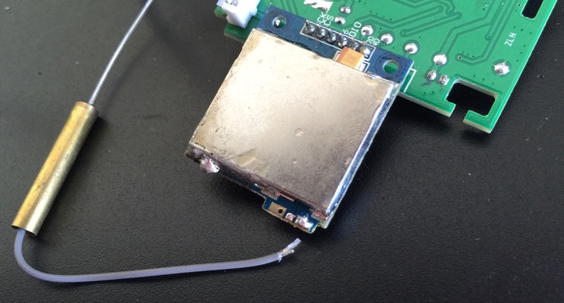
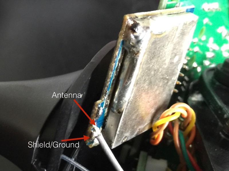
sadly, while handling the internals of the gt2b, the antenna just came off - does anyone know which of the 2 soldering spots is the shield/ground and which is the antenna? :(

screwup.jpg


p.s.: yea, I would just try it out, but the weather is nice for the next 2 days and I dont want to pick apart my board just yet - sadly on my board are the only ESCs I could use to test! :)
 
but the antenna is that transparent small cable in the middle, there is a shield/ground as well around the antenna cable within the grey cable - thats also going on the big soldering spot together with that shield within the grey cable?
 
I was thinking about that als well, unfortunately I don't have an other picture of that which shows this in detail. But from my memory the thinner (antenna) should be on the right and the thicker one (ground) on the left on your picture.
 
got another really weird problem with the trigger poti: whenever I connect it in ch2 and power up transmitter and receiver, the receiver led is doing on off cycles (error). if I also connect the steering poti in ch1, the transmitter/sender seems happy but the throttle control is borked - sometimes full throttle, then stopping, then some other completely random behavior. interesting thing is: when I connect the steering pot in ch2 instead (and just leave ch1 empty), I can use the motors without any issue, just regular throttle!

that made me think that there is something wrong with the trigger poti. when I measured its resistance, it seems like a regular functioning 5KOhm poti, nothing weird about it. If i measure the steering poti, it seems to be 5.5KOhm, so its a little different.

anyone got any idea what the problem could be? :|
 
I am not good at this stuff but BadWolf said he had to use resistors or it wouldn't work. Resistors on channel 1.
 
well, but if i keep the original steering poti on ch1, the setup is like in its original state. something must be weird about this throttle poti. :(

if anyone got an open gt2b, maybe do me a favour and tell me your throttle potis specifications! i already looked for a replacement poti (even though it seems to be functioning as intended), but didnt really find any so far.

ontop of those potis is a degree value - throttle is b5k50°, on the steering is b5k90°. thats probably telling me, its a 5kOhm poti with a control angle of 50° and/or 90° which fits quite well. throttle close/open is about 50°, full left/right is about 90°.

maybe anyone can tell me where I can find potis like that? usually they can turn between 270->300° (like the ones in the gt2b actually), but it looks as if they resistance is modulated from 0 to full within this 50°, respectively 90° angle.

bleh, dont feel like buying a 2nd gt2b because of that stupid poti :?
 
I should have one in the mail tomorrow - I'll try to get into it and check out the pots for you in the evening (EST).
Very strange problem.. Did you re-solder the antenna? Any chance you accidentally bridged any other connections on the board while doing that?

whitepony said:
...when I connect the steering pot in ch2 instead (and just leave ch1 empty), I can use the motors without any issue, just regular throttle!
You mean in this case it works with the steering input, not the trigger, right?

I'm not sure how sophisticated the controller's error checking is, but maybe measure the resistance of those pots in their natural state, as they are upon startup/connect. Do they seem reasonable? What if you hold the trigger down when turning it on - does the error code still flash?

Do you have some other 5k pot you can wire in for testing?
 
that would be great, Ill most likely just buy another GT2B because the poti seems not very "generic" with its 50° control angle.

the cause for the trouble MUST be in the throttle poti cause with the steering poti in its place, everything runs normal. nevertheless, the throttle poti acts like any regular 5k ohm poti would (from resistance measurements) ... cant seem to find anything weird about it. :?

think before I waste more of my time, ill just order another gt2b for 25€.
 
whitepony said:
...if anyone got an open gt2b, maybe do me a favour and tell me your throttle potis specifications! i already looked for a replacement poti (even though it seems to be functioning as intended), but didnt really find any so far.

ontop of those potis is a degree value - throttle is b5k50°...


Mine shows the same specs - b5k50°
 
used the poti from my 2nd GT2B :? and its all good now. actually it feels really good to play with the throttle. got the torqueboard 12S escs on lowest acceleration setting, so they arent very jerky, but just the right amount of "responsive". will be hard to choose between wiiceiver 2.0 and badwolf gt2b. wiiceiver got cruise control button which is just so awesome, gt2b has better throttle response.

for the other people who might accidently tear off their antenna - this is the original soldering position:

antennaGT2B.jpg


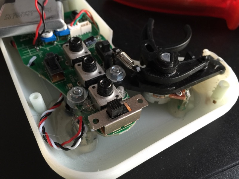
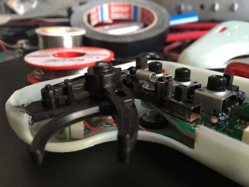
and this is my lever position and the way I fixated things inside - maybe additional pictures and perspectives will help people who also want to do it. great guide sl33py! my trigger just enters the badwolf enclosure when I hit full throttle and I feel that I got enough room for brakes as well without enclosure modifications. also changed a tiny detail when fixating the trigger: on the trigger, I carved out a little rectangle for the bind button on the main circuit board, so that the trigger comes to rest on top of the circuitboard instead of "on top of the bind button electronic enclosure". I also did not bend the tiny circuit board of the trigger poti - just removed its small fin with my dremel (like you did with the main curcuit board) and used the board as another hot glue point.
lever1.jpg

lever2.jpg


3d print is about to get painted now, natural 3d print finish isnt very pleasant. :)
 
Whitepony, what do you mean by one side goes on shield/ground and one on antenna? So the antenna cable is on left and shield/ground (the silvery bit?) on right?
 
Back
Top