This is a guide on how to modify a Golden Motors magic pie 2. Some of these modifications can be carried over to other brands of hub motors: 9 continent, Mxus(cell man), 500w golden motors etc. This is meant to be basic for beginners, to encourage people to help themselves and make cost effective mods, and make the most of fairly modest motors, more reliably and a more sustained duty cycle. The Magic pie 2 offers good torque/$ ratio, but any of these hubs will get similar results.
If you want more torque you need more phase amps. The cheap hub motors all suffer from very small phase wires, because of a lack of space to fit through the center axle hole or a very skinny slot in the axle. This means that you can not run high phase amp currents for sustained periods of time without melting the phase wires, which short out your controller and blows it up. Any voltage drop in the phase wires also only diminishes max rpm. So if you have a magic pie with the standard 6 fet internal controller and want to upgrade to a large external controller or need larger phase wires on your 9C clone, read on.
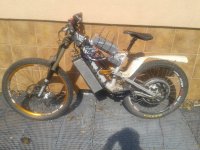
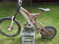
I have made a few of this style of warmed hub motors for several people both magic pie 2's and 9c clones. This ones for my little brother (first time e-biker), paired with a cell man A123 52V pack http://em3ev.com/store/index.php?route=product/product&path=35&product_id=106 with a 80A BMS and 24 fet controller and run at about 4000w
Comparison of standard 15awg or 1.5mm phase wire and new turnigy 8awg 8.4mm wire.
.jpg")
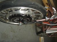
Step 1: Undo the right hand side plate using a 3mm allen key, and tap or pry off RH side plate. They are now silicone on and need a bit of persuasion!

Step 2: Now undo the LH side plate. Put an old block of wood on the floor and holding the hub or wheel from about 20cm high, push down, half hit, half push as straight as possible and the stator is removed.

Step 3: Hold stator by the axle in vice. If the motor has been used before the washers with small flats will have kicked up a small burr on the axle. Remove with a small file so you can remove the bearing later.

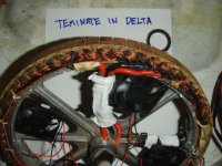
Step 4: cut back insulation on phase wire / motor winding join and unsolder. Wriggle off LH side cover, remove any circlips, Cut off hall wires at a convenient length to be re joined with new wires later, remove old wiring loom from axle and slip off bearing.
View attachment 12
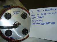
Step 5: Push 8awg wire over original phase wire, bind with a small thread of copper striped from an old wire off cut, and solder nice and hot. cover with 2 layers of heat shrink. Solder on new hall wiring to some shielded 7 -10 core shielded wire, and heat shrink cover. The 2 extra wires in the hall bundle is for a copper winding temperature probe, the other 2 wires can be used for 4 X 12V computer fans run in series.


Step 6: you need to make or have made on a small lathe a bearing adapter, to go from the standard 15 X 42 to a thin wall 30 X 42 x 7mm bearing. Make to these approximate dimensions in the photo. This important! it must be a tight(.05mm) interference fit onto the axle or the bush could spin and damage wires the bearing diameter should be minimum clearance slip fit. Drilling the wire holes must be done VERY carefully, or you will break out of the bush side walls. Drilling for slightly smaller 10awg phase wires lessens this chance a bit. You can also put a M3 or M4 grub screw in the bush to lock it to the axle for added security. Make a couple of bushes at the same time for spares or other motors. This drawing is for a magic pie bush but 9C clones are similar.

Step 7: Deburr any where wires could be damaged including axle slot and around the base of the hub/bush area. Silicon wire is excellent and flexible but the insulation cuts fairly easy on anything sharp!

Step 8: thread new wires through bush and press or tap on bush with hammer.


Step 9: you need to clearance the LH side plate for your new big wires out to approximately 31mm bore. If you do not have a lathe or one big enough you could file it out pretty quick is just clearance so is not that important. I try and leave a small lip left for the disk to locate on but its not that important.


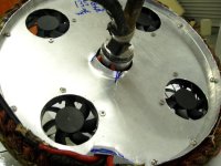
Step 10: Use a template and marker to mark out some pretty pattern for cooling holes. Use a drill press and or a battery drill. I have not ever broken a side plate jumping of or riding up flights of stairs or frocking up double jumps etc, but be sensible that you don't join dot to dot holes for cracks to propagate along. You can hog the holes out at an angle for dubious aero advantage but a small debur may help prevent cracks starting. 1/4" to 7mm holes seems ok.
View attachment 2

Step 11: You can remove the axle seal in the RH side plate with a screwdriver,the motor is full of holes now and this will do little. Hold the stator axle in the vice and wrap up phase wires with some tape and zip ties to hold it nice and compact against your axle so it does not rub on your disc brake center etc on the short turn radius out of the motor. assemble the motor left hand side plate 1st and make sure everything clears and is not rubbing. Now swap around in the vice with the RH pointing up, put on the flux ring/wheel over the stator making sure it is the correct way around/direction!! the MP2's have a wheel rim offset if you stuff this up you will have to pull it all apart again! (like i did) Watch your fingers don't get caught in between from the permanent magnets attraction to the stator iron. Bolt together side plates and make sure it all spins nice.

These mods take a little bit of time but offer a VERY large improvement in max phase amps,torque, and cooling and if you run high volts in a small wheel it really makes the most out of fairly humble motors for very little cost and are still fairly light. Please feel free to improve on this or add any advice etc.
Zappy
If you want more torque you need more phase amps. The cheap hub motors all suffer from very small phase wires, because of a lack of space to fit through the center axle hole or a very skinny slot in the axle. This means that you can not run high phase amp currents for sustained periods of time without melting the phase wires, which short out your controller and blows it up. Any voltage drop in the phase wires also only diminishes max rpm. So if you have a magic pie with the standard 6 fet internal controller and want to upgrade to a large external controller or need larger phase wires on your 9C clone, read on.
I have made a few of this style of warmed hub motors for several people both magic pie 2's and 9c clones. This ones for my little brother (first time e-biker), paired with a cell man A123 52V pack http://em3ev.com/store/index.php?route=product/product&path=35&product_id=106 with a 80A BMS and 24 fet controller and run at about 4000w
Comparison of standard 15awg or 1.5mm phase wire and new turnigy 8awg 8.4mm wire.
Step 1: Undo the right hand side plate using a 3mm allen key, and tap or pry off RH side plate. They are now silicone on and need a bit of persuasion!
Step 2: Now undo the LH side plate. Put an old block of wood on the floor and holding the hub or wheel from about 20cm high, push down, half hit, half push as straight as possible and the stator is removed.
Step 3: Hold stator by the axle in vice. If the motor has been used before the washers with small flats will have kicked up a small burr on the axle. Remove with a small file so you can remove the bearing later.
Step 4: cut back insulation on phase wire / motor winding join and unsolder. Wriggle off LH side cover, remove any circlips, Cut off hall wires at a convenient length to be re joined with new wires later, remove old wiring loom from axle and slip off bearing.
View attachment 12
Step 5: Push 8awg wire over original phase wire, bind with a small thread of copper striped from an old wire off cut, and solder nice and hot. cover with 2 layers of heat shrink. Solder on new hall wiring to some shielded 7 -10 core shielded wire, and heat shrink cover. The 2 extra wires in the hall bundle is for a copper winding temperature probe, the other 2 wires can be used for 4 X 12V computer fans run in series.
Step 6: you need to make or have made on a small lathe a bearing adapter, to go from the standard 15 X 42 to a thin wall 30 X 42 x 7mm bearing. Make to these approximate dimensions in the photo. This important! it must be a tight(.05mm) interference fit onto the axle or the bush could spin and damage wires the bearing diameter should be minimum clearance slip fit. Drilling the wire holes must be done VERY carefully, or you will break out of the bush side walls. Drilling for slightly smaller 10awg phase wires lessens this chance a bit. You can also put a M3 or M4 grub screw in the bush to lock it to the axle for added security. Make a couple of bushes at the same time for spares or other motors. This drawing is for a magic pie bush but 9C clones are similar.
Step 7: Deburr any where wires could be damaged including axle slot and around the base of the hub/bush area. Silicon wire is excellent and flexible but the insulation cuts fairly easy on anything sharp!
Step 8: thread new wires through bush and press or tap on bush with hammer.
Step 9: you need to clearance the LH side plate for your new big wires out to approximately 31mm bore. If you do not have a lathe or one big enough you could file it out pretty quick is just clearance so is not that important. I try and leave a small lip left for the disk to locate on but its not that important.
Step 10: Use a template and marker to mark out some pretty pattern for cooling holes. Use a drill press and or a battery drill. I have not ever broken a side plate jumping of or riding up flights of stairs or frocking up double jumps etc, but be sensible that you don't join dot to dot holes for cracks to propagate along. You can hog the holes out at an angle for dubious aero advantage but a small debur may help prevent cracks starting. 1/4" to 7mm holes seems ok.
View attachment 2
Step 11: You can remove the axle seal in the RH side plate with a screwdriver,the motor is full of holes now and this will do little. Hold the stator axle in the vice and wrap up phase wires with some tape and zip ties to hold it nice and compact against your axle so it does not rub on your disc brake center etc on the short turn radius out of the motor. assemble the motor left hand side plate 1st and make sure everything clears and is not rubbing. Now swap around in the vice with the RH pointing up, put on the flux ring/wheel over the stator making sure it is the correct way around/direction!! the MP2's have a wheel rim offset if you stuff this up you will have to pull it all apart again! (like i did) Watch your fingers don't get caught in between from the permanent magnets attraction to the stator iron. Bolt together side plates and make sure it all spins nice.
These mods take a little bit of time but offer a VERY large improvement in max phase amps,torque, and cooling and if you run high volts in a small wheel it really makes the most out of fairly humble motors for very little cost and are still fairly light. Please feel free to improve on this or add any advice etc.
Zappy


 ) or usually a KEB 8KW Kelly controller, which has a LOT better throttle modulation.