How to read out this torque sensor

sven

1 µW
Joined
Jun 27, 2020
Messages
3
I got hold of an old Gazelle E-bike and my goal is to reverse engineer the inner workings and make it into a handthrottle bike instead of a pedal assistant.

The middrive is a panasonic NUA002k11.
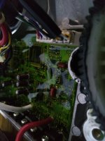
I opened it up and this is how it looks on the inside:
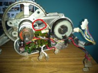
ebike.JPG
pcb.jpg
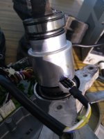
sens.jpg

The reason for this thread is that I'd like to be able to understand how the torque sensor works electronically.
The connector going to the torque sensor is circled in the picture and is a 3-wire connector.
when the sensor is disconnected from the main pcb I measure the following voltages on the pcb: 1,4v 0v 0v.
when measuring the resistance of the sensor I measure: 80 ohm, 80 ohm and 160 ohm.

I didn't found the sensors name but I found one post where the inner workings of - what seems to be the same sensor - get explained: https://www.pedelecforum.de/forum/i...nic-antrieb-kadenz-oder-momentgesteuert.4789/

So from the information that the torque sensor consists of 2 coils wounded around the shaft I deduced that the pins would be left-coil connection, center-tap , right coil connection assuming the coils are connected in series.

At first I was expecting a VCC, GND and analog out but that doesn't seems to be the case. I'm wondering right now which circuit should be put between a microcontroller and the sensor pins to be able to read the torque. (I am not able to reverse engineer the PCB because there's a thick layer of glue on top)

If anyone has some advice on how to read out the torque sensor, how it exactly works or what it's specific name is please help me!
 
At a guess, you're connecting directly to the strain gauges, in which case you'd need to buy or build amplifiers for them. See Justin_LE's weight sensing longboard thread on how you can do that.

If possible, you may wish to use the electronics already in the Gazelle system, so you don't have to figure out how to read the gauges to get a usable result. The ssytem should already be able to read them and be outputting one of the several types of signal listed here:
https://www.ebikes.ca/getting-started/pas-options.html#torque-sensors
(some analog voltage range, typically)
that you can then tap off of to do whatever it was you wanted to do with this.


FWIW, your image link gives me "Website blocked due to trojan". If you instead attach all images/etc directly to your post in the attachments tab, then anyone that can see your post can see your images.
 
amberwolf said:
At a guess, you're connecting directly to the strain gauges, in which case you'd need to buy or build amplifiers for them. See Justin_LE's weight sensing longboard thread on how you can do that.

If possible, you may wish to use the electronics already in the Gazelle system, so you don't have to figure out how to read the gauges to get a usable result. The ssytem should already be able to read them and be outputting one of the several types of signal listed here:
https://www.ebikes.ca/getting-started/pas-options.html#torque-sensors
(some analog voltage range, typically)
that you can then tap off of to do whatever it was you wanted to do with this.


FWIW, your image link gives me "Website blocked due to trojan". If you instead attach all images/etc directly to your post in the attachments tab, then anyone that can see your post can see your images.

Thank you for your advice!
I attached the image directly to the thread and added an extra image of the sensor itself.
Using the electronics on the main pcb is a good idea but would not be possible in this case. You could see from the image I now added that the pcb is glued in the drive and there's 5mm glue on top. The traces from the sensor go to some smd resistors and dissapear through some vias. Most nearby chips are not readable but there's an 8 pin chip that looks like an opamp.

In my research for the sensor I found an issue where someone had trouble with broken connections of this sensor and that person then openend up the sensor (visualy same sensor and same connection wire colors) and there were visually two coils. Sorry but I couldn't find the link anymore. What I want to say is that I don't think that this sensor works on the principle of strain gauges. If I would be wrong I could connect it to a HX711 I have laying around but I'd need 4 pins (or 2) and have 3.
 
If it's actually coils, then that means there's a magnet in there, probably a ring type, polarized in a pattern, on the crankshaft. (rather than a bunch of separate ones). Most likely this gives a sinewave pattern during rotation, on one coil, and a cosine on the other (a common rotary encoder type).

Usually this would just give you cadence, but if they can detect the current changes in each coil from distortions of the shaft due to pedal torque, then that could be used to determine torque, with the reference of no torque already known and calibrated (probably every time you start up the bike, it would tell you to remove your feet from the pedals for a few seconds so it can do this). Depending on the setup it could have a 90 degree (sin/cos) difference between coils with no torque, or zero degrees difference, and then any torque applied would be whatever is different from that.

It could use just current, and not a rotational field relationship, so taht any difference in amplitude between the two coils means there is torque , and how much torque that is is the amount of difference.

Based on the readings you got, the two coils are connected at one end, to each other and one of the wires, and the other ends are separately wired out. So a common supply voltage (or current) would be sent in to both, then the other end would connect to something (differential amplifier probably) to determine the difference between them, and call that torque detected.


BTW, potting is often relatively easy to remove with the right chemicals. If it is clear conformal coat, acetone or paint thinners typically remove it. Really thick may require soaking for up to several hours to soften it. If it is resin, then ATF for cars may, or brake fluid. (sometimes these may also dissolve the resins IC chips are made of, so keep an eye on it). If it is silicone, you might be stuck with picking it out...but it tears easily so it comes off in chunks, and is just timeconsuming, especially since you can se thru yours, to avoid hitting components with the pick.
 
Thank you amberwolf once again for sharing your ideas and approaches on how to solve my problem.

Just now I tried to access a link that's not longer working throug the wayback machine and was able to get a screenshot from 2012 from the website which contains some usefull information:
https://web.archive.org/web/20120123040506/http://myweb.tiscali.co.uk:80/flecc/motorunit1.html

The sensor is indeed a center tapped coil which is powered and some irregulaties on the shaft introduce disturbances in the coil.
the time differences between those disturbances for each coil are due to torque being applied to the shaft.

I assume those disturbances result in small voltage changes over the coils so an amplifier musted be used to read those. Further I assume the microcontroller on the board would implement to logic to decide wether and how much one signal delayed regarding the other one.

Uncertainties:
How I could fake the signal or read the real signal. From some measurements a concluded that the two coils are connected to VCC through a 1K resistor. The connection from the centertap to GND is unknown (seems to be capacitive).

Note: removing the potting is a good idea but I rather wouldn't do so. I think I would break the pcb and would like to have everything protected by the sillicone as now.
 
I've quoted the relevant section of that link below, in case it goes away at some point.

My guess is they drive the coils with an AC signal (set of pulses, probably 50% DC, probably in the kHz range somewhere; you'd have to measure the frequency from the controller in operation). Most likely the pulses are opposite on each one, to create a 180-degree-out-of-phase signal set. The page says there's not a magnet but rather the metal "hatched" zones; these change the inductance of the coils as they pass and so change the phase relationship between the two sets that would otherwise be complletely out of phase. There is probably a differential op-amp with it's inputs on the two coils'' non-common ends. If they're at 180 degrees, unmodulated, they will cancel out, and the opamp gets zero volts. If they're at any other relationship, there wil be a voltage present, and the opamp will magnify that by whatever it needs to to get control voltage the system can use for a "throttle" input to the controller.


Then there's a separate cadence sensor, covered in the last paragraph.


The pedelec drum is a sealed assembly, but for completeness I've broken it apart to show it's inner workings. Inside the drum is this centre tapped twin coil winding, it's three wires going to the small white connector. The windings sit over the two hatched zones of the inner metal sleeve arrowed above. Since the sleeve turns with the pedal shaft, the raised metal areas of the hatching disturb the magnetic field generated by the coils, thus indicating rotation by feedback of the disturbance. As
the bike is pedalled without power, the drive to the pedelec sleeve is from the shaft splines, loaded against the pedalshaft freewheel driving the chainwheel. This imparts a left driven twisting/warping motion to the sleeve, giving a minute differential to the left hand and right hand disturbance of the two coils magnetic fields. In contrast, when the motor is running full on and pedal thrust is minimal, the twisting motion doesn't exist since the load of the pedalshaft freewheel is removed and the sleeve is free to spin, and therefore the magnetic fields are equalised. Between these two are an infinitely variable set of states which can be read by the cpu in setting the motor contribution to the drive needs. Thus the pedelec sensor acts like a strain gauge to sense rider effort as well as rotation.

In partnership with this, the Hall sensor that is an extension of the mainboard is reading the 24 magnets on the gearwheel of the unit's chain sprocket shaft, and is therefore detecting rotation speed, indicating road speed in top gear to enable the cpu to phase down power at around 13 mph and cut it at the 15 mph legal limit. On a 3 speed Twist at 13 mph, the magnets pass the Hall sensor at a rate of just over 77 per second, therefore giving more than enough feedback to give a very high degree of road speed accuracy. That same magnet gearwheel is also the output drive from the motor when that is operating. Since the only drive connection between the pedalshaft drive and the output shaft is the chain, tensioned by a spring loaded idler, variations in the contributions from each can be sensed as tiny changes in relative speeds of the two, this again probably assisting the cpu in managing the motor behaviour. The net result is a motor control system that is superior to any other yet in pedelec bikes, somewhat bionic in it's nature as it responds to rider input by adding power to the muscle power on pedal strokes.
 
I played with my bike (36V Flier) and find that attaching 10Kohm resistor between common and one of coils (between white and yellow for me) of torque sensor gives you pretty much full power emulating hard pedaling. My guess is torque sensor causes small voltage drop (very small) on one of its coils, which in turn gets detected by the cpu and is proportional to pedaling strength. So dropping voltage by 10K resistor is sufficient to cheat cpu that you are pedaling hard. I have a 5V relay connect that resistor. Relay is hooked up through a small transistor to BIKE PUSH button line to trigger the relay. I don't know if your bike has a push button, but if it does that is your throttle. Yo don't need power regulation because there just isn't enough power to adjust. Motor is too weak. Al you need is on/off. If you insist on having throttle you are going to have to connect a variable resistor instead of 10K. Its value should be between 10K (full power) and about 16-17K (min power). I think that's too much trouble. My button works just fine and now I enjoy smooth sailing without having to pedal :)
 
I've quoted the relevant section of that link below, in case it goes away at some point.

My guess is they drive the coils with an AC signal (set of pulses, probably 50% DC, probably in the kHz range somewhere; you'd have to measure the frequency from the controller in operation). Most likely the pulses are opposite on each one, to create a 180-degree-out-of-phase signal set. The page says there's not a magnet but rather the metal "hatched" zones; these change the inductance of the coils as they pass and so change the phase relationship between the two sets that would otherwise be complletely out of phase. There is probably a differential op-amp with it's inputs on the two coils'' non-common ends. If they're at 180 degrees, unmodulated, they will cancel out, and the opamp gets zero volts. If they're at any other relationship, there wil be a voltage present, and the opamp will magnify that by whatever it needs to to get control voltage the system can use for a "throttle" input to the controller.


Then there's a separate cadence sensor, covered in the last paragraph.
I can't believe how smart you guys are. I can't believe it you're like electrical alchemist.
At least Amber is anyway.yyyyyyy
 
Back
Top